Behringer CAT CAT Quick Start Guide - Page 7
an AR Attack=Release transient envelope. The BYPASS - used
 |
View all Behringer CAT manuals
Add to My Manuals
Save this manual to your list of manuals |
Page 7 highlights
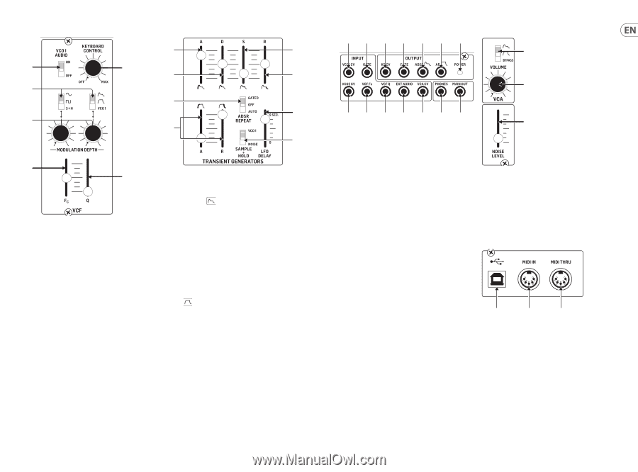
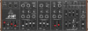
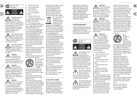
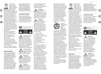
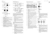
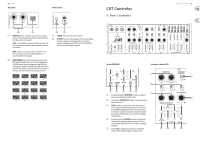
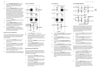
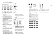
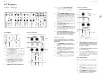
12 CAT VCF Filter Section (22) (24) (25) TRANSIENT GENERATORS Section (28) (30) (23) (29) (31) (33) (35) (32) (34) (26) (27) The ADSR (Attack-Decay-Sustain-Release) transient generator creates a detailed voltage transient every time a key is depressed. The voltage transient is shaped by the ATTACK, DECAY, SUSTAIN and RELEASE sliders, and the ADSR voltage transient is available at all switches marked . (28) ATTACK slider controls the shape of the note attack up to (22) VCO1 AUDIO switch, when in the OFF position, takes VCO1 an initial fixed peak when a key is depressed. completely out of the final audio mix. (29) DECAY slider controls how quickly the envelope drops (23) KEYBOARD CONTROL knob determines how closely the from the initial fixed peak. keyboard controls the low-pass filter cutoff frequency (FC). (30) SUSTAIN slider controls the level at which the envelope (24) VCF FC MODULATION SOURCE switches select waveforms holds after the initial decay following the fixed peak. to modulate the VCF cutoff frequency. (31) RELEASE slider controls the envelope shape following the (25) MODULATION DEPTH knobs control the amount of key release. waveform applied to the VCF cutoff frequency. The AR (Attack-Release) transient generator works similarly to the (26) FC (FILTER CUTOFF) slider controls the low-pass filter's ADSR generator, but with less detailed control over the transient cutoff frequency. The filter will cut off more and more envelope. The AR voltage transient is available at all switches treble frequencies as the slider is moved downward. At the marked . full upper setting, no treble frequencies are being cut off. (27) Q (RESONANCE) slider affects the low-pass filter's timbre (32) ATTACK-RELEASE sliders control the transient slope for when a key is depressed (ATTACK) and when that key is by emphasizing harmonics around the cutoff frequency. released (RELEASE). At the full upper setting, the VCF will oscillate and no other sounds will come through the filter. (33) ADSR REPEAT switch causes any ADSR setting to repeat at a speed determined by the LFO. In the GATED position, the transient will only repeat while the key is held down. In the AUTO position, the transient repeats even if the key is released. (34) SAMPLE + HOLD switch selects the source that will be sampled by the automatic Sample-and-Hold function. In the VCO1 setting, the VCO1 mix setting will be sampled. In the NOISE position, the noise generator output is sampled to produce a random output pattern. (35) LFO DELAY slider controls the amount of time it takes for the LFO SINE wave output to reach its maximum after a key is depressed. Additional Controls and Connections (42) (41) (37) (38) (39) (40) (36) Other Controls (50) Quick Start Guide 13 (51) (43) (44) (45) (46) (47) (48) (49) (36) POWER LED lights up to show the unit has been powered on. (37) KB CV jack routes keyboard control signals to external devices. (38) GATE jack sends out an internal control voltage signal. (39) ADSR jack sends out an internal control voltage signal. (40) AR jack sends out an internal control voltage signal based on the current settings of the ATTACK-RELEASE sliders. (41) GATE routes in external control voltage signals for the GATED setting of the ADSR REPEAT switch. (42) VCO1 CV routes in external control voltage signals for the VCO1 and VCO2 frequency setting. (43) VCO2 CV routes in external control voltage signals for the VCO2 frequency setting. (44) VCF Fc routes in external control voltage signals for the VCF Fc setting. (45) VCF Q jack routes in external control voltage signals for the VCF Q setting. (46) EXT. AUDIO input connects any external line-level audio source to this 3.5 mm input. (47) VCA CV jack routes in external control voltage signals for the VCA VOLUME control. (48) PHONES jack connects to headphones with a 1/8" TRS stereo connector. (49) MAIN OUT uses a 3.5 mm TR connection to output the main audio output. Typically it can be patched to the audio input of another CAT or to the audio inputs of other modular synthesizer equipment. If you are using the CAT in a Eurorack, then this is the main output, as the rear panel output connectors are not used. (52) (50) VCA switch determines whether the VCA uses an ADSR (Attack-Decay-Sustain-Release) transient envelope or an AR (Attack=Release) transient envelope. The BYPASS setting completely bypasses the VCA so that the sound level on the output is constant. (51) VCA VOLUME knob controls the final output volume. (52) NOISE LEVEL slider controls the amount of white noise mixed into the VCF. MIDI Section (53) (54) (55) (53) USB PORT allows connection to a computer over a USB type B connection. The CAT will show up as a classcompliant USB MIDI device, capable of supporting MIDI in and out. (54) MIDI IN receives MIDI data from an external source over a 5-pin DIN connector. This will commonly be a MIDI keyboard, an external hardware sequencer, a computer equipped with a MIDI interface, etc. (55) MIDI THRU uses a 5-pin DIN jack is used to pass through MIDI data received at the MIDI INPUT. This data will commonly be sent to another synthesizer to run a Poly Chain or to a drum machine assigned to a different MIDI Channel.
-
 1
1 -
 2
2 -
 3
3 -
 4
4 -
 5
5 -
 6
6 -
 7
7 -
 8
8 -
 9
9 -
 10
10 -
 11
11 -
 12
12 -
13
-
14
-
15
-
16
-
17
-
18
-
19
-
20
-
21
-
22
-
23
-
24
-
25
-
26
-
27
-
28
-
29
 |
 |