Behringer FBQ1000 Manual - Page 10
Problems Do Have A Cause ..., 9. MIDI Control - feedback destroyer
 |
View all Behringer FBQ1000 manuals
Add to My Manuals
Save this manual to your list of manuals |
Page 10 highlights
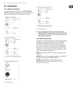
10 FEEDBACK DESTROYER FBQ1000 User Manual 8. Problems Do Have A Cause ... Feedback is one of the major problems encountered in live P.A. applications. In a worst-case scenario every microphone signal passing an amplifier can cause feedback. Still, there's a lot you can do even before the show begins: • Place the microphones at some distance to the FOH and monitor speakers • Make sure that the levels of the microphone channels are adjusted correctly (see user's manual of your console) • Use the microphones according to their polar patterns (e.g. omnidirectional, cardioid, super-cardioid) • Poor room acoustics should be improved. Tiled walls and floors, which are highly reflective, can be covered with curtains or carpet • Use a graphic equalizer to adapt the overall sound to the room acoustics • To a certain degree, feedback can also be suppressed manually with a graphic EQ 9. MIDI Control Use the MIDI key combination to select the MIDI parameters you wish to adjust. To do so, press and keep the IN/OUT and STORE keys at the same time. All parameters can be edited with the JOG WHEEL and these two keys. The MIDI menu includes six pages, which you can select by pressing the IN/OUT key (forward) and the STORE key (backward) several times. On the first page, you can select the MIDI channel. The DISPLAY reads a small "c" (= channel). The JOG WHEEL adjusts a channel from 1 through 16. To switch off the MIDI function, simply select "0" (displayed as "-"). On the second page, you can select MIDI Omni mode, i.e. the unit transmits/ receives on all 16 MIDI channels. The DISPLAY reads "O" (= Omni). Use the JOG WHEEL to activate ("1") or deactivate ("0") MIDI Omni mode. The third page allows for the configuration of controller commands. On its right-hand side, the DISPLAY reads a capital "C" (= Controller). The JOG WHEEL selects one of the five controller modes shown below: Display 0 1 2 3 4 Mode No controller data are transmitted Controller data are received but not transmitted Controller data are transmitted but not received Controller data are transmitted and received As 3, with additionally the automatic filter parameters Tab. 9.1: Controller settings ◊ When you choose value "4", the FEEDBACK DESTROYER will send the automatic filter values in addition to the parameter values. For details on the controller functions, see Tab. 11.5 in the appendix. The fourth page gives you access to the Program Changes. The DISPLAY reads a capital "P" (= Program). Four modes are available, which can be selected with the JOG WHEEL, as follows: The fifth page of the MIDI menu shows the "Store Enable" flag represented by a capital "S" in the DISPLAY. Available values are "0" and "1". If set to "1", the FEEDBACK DESTROYER receives controller 18 as a direct save command, i.e. the current settings will be stored without further confirmation in the preset number that corresponds to this controller value. If set to "0", the FBQ1000 ignores all incoming commands referring to controller 18. ◊ ATTENTION! Store Enable mode has been designed to transmit several presets as conveniently as possible from an external PC to the FEEDBACK DESTROYER. In this mode, it is possible that stored presets will be replaced or altered if controller 18 messages are sent via MIDI! We therefore recommend that you disable this mode as soon as the intended data transfer has been completed. During power-up, this mode is automatically disabled (mode "0"). On the sixth, and presently the last page you can access the "System Exclusive" functions, which is indicated by a "d" (= dump) in the DISPLAY. To the left of this "d", you can see a "0" if no sys-ex data can be received or transmitted. When you enter mode "1", the FBQ1000 will be able to receive sys-ex data. In mode "2", the FBQ1000 is ready to dump its entire memory contents with all parameter settings to an external MIDI storage medium. Start your sequencer software, and press the STORE key. To load the data back, select mode "1", and start your sequencer software to restore the settings in your FEEDBACK DESTROYER. If you press the IN/OUT key again on the sixth page, the FEEDBACK DESTROYER quits MIDI mode. You can also use any other key to leave the MIDI setup menu. The full-featured MIDI implementation of the FEEDBACK DESTROYER allows for easily integrating the unit into any MIDI system. • MIDI IN All MIDI data sent to the FBQ1000 (sequencer, MIDI foot controller, etc.) are received via the MIDI IN jack. For example, if you wish to use the FBQ1000 as an effects device for your guitar rack, you can connect the MIDI IN jack to a MIDI foot controller that allows for selecting program presets. If your rack includes another MIDI effects device, the data sent from the MIDI foot controller can be passed on to that device through the MIDI THRU port of the FEEDBACK DESTROYER. • MIDI THRU The MIDI THRU jack is used to loop through incoming MIDI data, i.e. any controller data received at the MIDI IN of the FEEDBACK DESTROYER will be transmitted via the MIDI THRU jack to other MIDI devices/instruments. • MIDI OUT The MIDI OUT jack allows for transmitting MIDI data that originate from the FBQ1000. The FEEDBACK DESTROYER Design Editor software enables you to control the FBQ1000 from an external PC. What is more, you can use the FEEDBACK DESTROYER to control the editor software, so that both units communicate with each other. Download the editor free of charge from our web site at behringer.com. Display 0 1 2 3 Mode No program change data are transmitted Program change data are received but not transmitted Program change data are transmitted but not received Program change data are transmitted and received Tab. 9.2: Program change settings
-
 1
1 -
2
-
3
-
4
-
 5
5 -
 6
6 -
 7
7 -
 8
8 -
 9
9 -
 10
10 -
 11
11 -
 12
12 -
 13
13 -
 14
14 -
 15
15 -
16
-
17
 |
 |