Behringer FBQ1000 Manual - Page 7
FBQ1000 Architecture: Presets, Filters, Operating Modes, FUSE HOLDER / VOLTAGE SELECTOR - setup
 |
View all Behringer FBQ1000 manuals
Add to My Manuals
Save this manual to your list of manuals |
Page 7 highlights
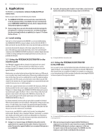
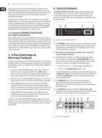
7 FEEDBACK DESTROYER FBQ1000 User Manual (5) With the JOG WHEEL, a continuous rotary control, you can freely edit the selected parameters. Turn the wheel clockwise to increase the values, or counterclockwise to reduce them. (6) With the FILTER SELECT key activated, you can use the Jog Wheel to select one of the 12 filters per channel. Subsequently, you can edit the filters. (7) The FILTER MODE key gives you access to the four operating modes for the individual filters: "Off mode (OF)", "Parametric EQ (PA)", "Single-Shot mode (SI)" and "Auto mode (AU)". Please read chapter 6 "Operating Modes of the FBQ1000". ◊ Pressing the FILTER MODE and GAIN keys simultaneously allows you to adjust the sensitivity of the feedback suppression trigger circuit. The setting range is from -3 through -9 dB and can be adjusted with the JOG WHEEL. The default value is -6 dB, as this setting usually delivers the best results. (8) Use the ENGINE L key to select the left audio channel. (9) Use the ENGINE R key to select the right audio channel. If you wish to process both channels at the same time (Couple mode), press both Engine keys together. In Couple mode both ENGINE LEDs light up. Whenever you edit one of the two audio channels and then switch to Couple mode, the parameters of the active channel will be copied to the other, i.e. if you press ENGINE L before ENGINE R, left will be copied to right. Items (10) through (13) refer to Parametric EQ mode only (see chapters 5 and 7.3). (10) Press the FREQUENCY key to select the frequency you wish to process. The adjustable frequency range is from 20 Hz through 20 kHz, which are split up by the FBQ1000 into the 31 standard ISO values of a graphic equalizer (see chapter 11.1 in the appendix). (11) The FINE key allows you to fine tune the standard ISO frequencies (in 1/60octave steps), within a tuning range of 1/3 octave (-9/60 to +10/60). (12) BANDWIDTH determines the filter bandwidth (Q factor) of the selected filter. This adjustable filter quality ranges from 1/60 octave to 2 octaves (120/60 octave). (13) The GAIN key sets the desired boost/cut of the selected filter in dB (+16 dB/-48 dB). (14) The IN/OUT key allows for optional bypassing of the parametric filters or all filters. By shortly pressing the IN/OUT key, only the Parametric EQ filters will be deactivated, and the green LED goes out. Hold down the key for about two seconds to deactivate all filters. This "Total Bypass" mode is indicated by the cyclic flashing of the green LED. Another short IN/OUT key press reactivates all filters. Additionally, the LED flashes when relevant MIDI data are being received. ◊ If the control LED of the IN/OUT key flashes, all functions (including all automatic filters used for feedback suppression) are disabled ("Total Bypass"). In all other modes, at least the Single-Shot and Auto filters are active ("Bypass"). ◊ Please use the "Total Bypass" function only with caution, because the deactivation of the filters possibly unlocks suppressed feedback. (15) Any modifications made to a preset can be stored with the STORE key, in accordance with the number shown by the Display. Ten presets are available on the FBQ1000. Press the IN/OUT and STORE keys simultaneously to enter MIDI Setup mode. (16) Use the POWER switch to switch the FEEDBACK DESTROYER on or off. (22) (21) (20) (19) (17) (18) Fig. 4.3: Rear panel connectors and control elements (17) Use the OPERATING LEVEL switch to change from home recording level (-10 dBV) to studio level (+4 dBu), and vice versa. The level meters are adapted automatically to the selected nominal level, so that the FEEDBACK DESTROYER will always work in its optimum operating range. (18) These are the balanced INPUTS of the FBQ1000, which are on 1/4" TRS and XLR connectors. (19) The two OUTPUTS of your FEEDBACK DESTROYER are also on balanced 1/4" TRS and XLR connectors. (20) SERIAL NUMBER. Please take the time to fill in and return the warranty card within 14 days after the date of purchase, so as to benefit from our extended warranty. Or use our online registration option available on the World Wide Web at behringer.com. (21) The FBQ1000 features a complete set of MIDI functions. In addition to the usual MIDI IN and MIDI OUT ports, the MIDI THRU allows you to loop through MIDI data. (22) FUSE HOLDER / VOLTAGE SELECTOR. Please make sure that your local voltage matches the voltage indicated on the unit, before you attempt to connect and operate the unit. Blown fuses may only be replaced by fuses of the same type and rating. Some models allow for inserting the fuse holder in two different positions, in order to switch over from 230-V to 115-V operation, and vice versa. Please note that for 115-V operation outside Europe, you need to use a fuse of a higher rating (see chapter 1.2). Use the enclosed power cord to connect the unit to the mains. 5. FBQ1000 Architecture: Presets, Filters, Operating Modes In order to avoid confusion, let us give you a concise description of the FBQ1000's operating principle, so as to make the three relevant points clear right from the start. Example: You have set up your P.A. system and connected all signal sources to the console. The FBQ1000 has been inserted into the monitor path (see fig. 2.1) or in single channel or sub-group inserts (see fig. 2.2); after power-up preset 1 was loaded with the JOG WHEEL. Now, you can start to purposefully produce feedback, as described in chapter 3. Depending on the room acoustics, various feedback frequencies can occur. What exactly does the FBQ1000 do? As can be seen from table 11.3, each of the ten presets on your FBQ1000 comprises 24 separate filters, which can, however, be set to different operating modes: In our example, the first nine filters of the selected preset are set to Single-Shot mode ("SI", see chapter 6.3). This mode is designed to detect feedback frequencies at fixed resonance values, and to suppress them consistently. So, these filters cannot be unlocked (status "LO" (locked)). Their bandwidth and gain reduction can be adapted if required, however, the frequency setting remains the same. In our example, the FBQ1000 is used to prevent nine fixed frequencies from "making trouble".
-
 1
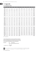
1 -
 2
2 -
 3
3 -
 4
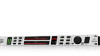
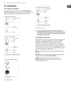
4 -
 5
5 -
 6
6 -
 7
7 -
 8
8 -
 9
9 -
 10
10 -
 11
11 -
 12
12 -
13
-
14
-
15
-
16
-
17
 |
 |