Behringer FBQ1000 Manual - Page 11
Installation, Audio connections
 |
View all Behringer FBQ1000 manuals
Add to My Manuals
Save this manual to your list of manuals |
Page 11 highlights
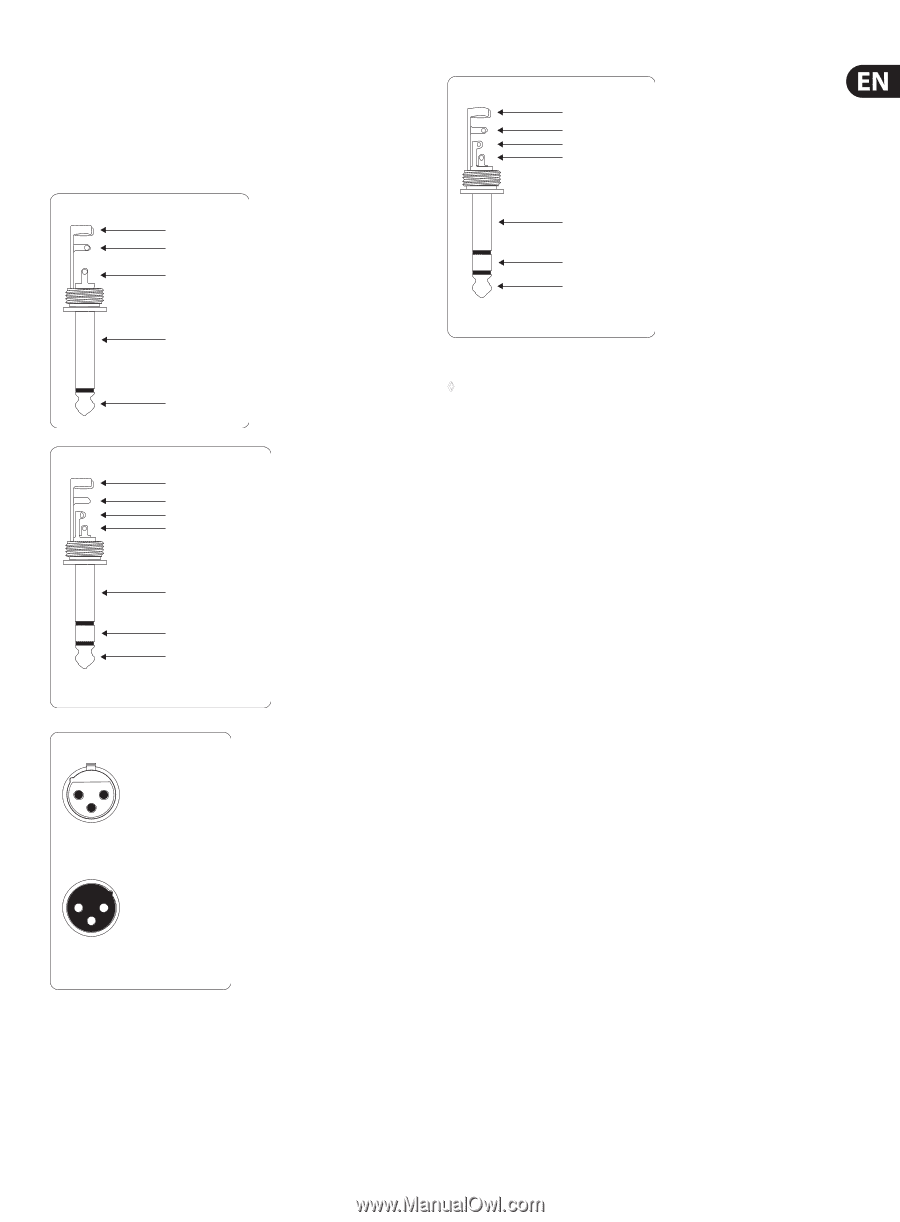
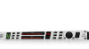
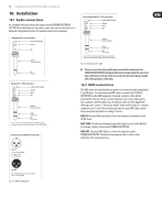
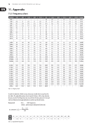
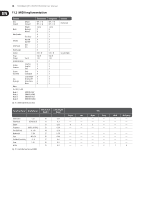
11 FEEDBACK DESTROYER FBQ1000 User Manual 10. Installation 10.1 Audio connections As a standard, the audio inputs and outputs on the BEHRINGER FEEDBACK DESTROYER are fully balanced. If possible, connect the unit to other devices in a balanced configuration to allow for maximum interference immunity. Insert send return ¼" TRS connector strain relief clamp sleeve ring tip Unbalanced ¼" TS connector strain relief clamp sleeve tip sleeve (ground/shield) tip (signal) Balanced ¼" TRS connector strain relief clamp sleeve ring tip sleeve ground/shield ring cold (-ve) tip hot (+ve) For connection of balanced and unbalanced plugs, ring and sleeve have to be bridged at the stereo plug. Balanced use with XLR connectors 21 3 input 1 = ground/shield 2 = hot (+ve) 3 = cold (-ve) 12 3 output For unbalanced use, pin 1 and pin 3 have to be bridged Fig. 10.1: Different plug types sleeve ground/shield ring return (in) tip send (out) Connect the insert send with the input and the insert return with the output of the e ects device. Fig. 10.2: Wiring an insert cable ◊ Please ensure that only qualified persons install and operate the FEEDBACK DESTROYER. During installation and operation the user must have sufficient electrical contact to earth. Electrostatic charges might affect the operation of the unit. 10.2 MIDI connections The MIDI connectors found on the rear panel are on internationally standardized 5-pin DIN jacks. You need dedicated MIDI cables to connect the FEEDBACK DESTROYER to other MIDI equipment. Normally, complete cables will be purchased for this use, but you can also make your own, using a high-quality two-conductor shielded cables (e.g. microphone cable) and two rugged 180° DIN plugs: pin 2 (center) = shield, pins 4 and 5 (right and left of pin 2) = internal conductors, pins 1 and 3 (the two outer pins) are not used. MIDI cables should have a maximum length not exceeding 15 meters. MIDI IN: Receives MIDI control data. The receive channel is determined in the SETUP menu. MIDI THRU: Provides an unchanged copy of the signal received at the MIDI IN, for example, to daisy-chain several FEEDBACK DESTROYER. MIDI OUT: Transmits MIDI data to a connected computer or other FEEDBACK DESTROYER. Transmitted are program data as well as status information for signal processing.
-
 1
1 -
2
-
3
-
4
-
5
-
 6
6 -
 7
7 -
 8
8 -
 9
9 -
 10
10 -
 11
11 -
 12
12 -
 13
13 -
 14
14 -
 15
15 -
 16
16 -
17
 |
 |