Behringer FBQ1000 Manual - Page 6
A Few Quick Steps to Eliminate Feedback, 4. Control Elements, Using the FEEDBACK DESTROYER
 |
View all Behringer FBQ1000 manuals
Add to My Manuals
Save this manual to your list of manuals |
Page 6 highlights
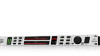
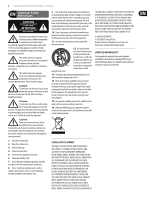
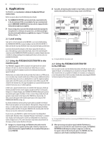
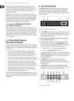
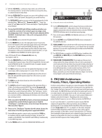
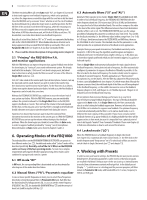
6 FEEDBACK DESTROYER FBQ1000 User Manual Ideally, your mixer has sub-groups with dedicated insert points to connect the FBQ1000! Route all channels that are susceptible to feedback (e.g. all vocal mics) to one sub-group. While the other signals (e.g. line level signals, low-level instrumental mics) pass unaffected, all critical microphone channels are monitored by the FBQ1000. If your mixer has no sub-group inserts, we recommend that you connect the FBQ1000 as follows: connect the sub-group output to one input on the FBQ1000, and the corresponding output to a free line input of a mixing console channel or one of the Aux Return inputs on the console. As long as ENGINE L and ENGINE R are not linked, you would even have the second channel of your FEEDBACK DESTROYER free for other applications (e.g. channel inserts). 4. Control Elements The BEHRINGER FEEDBACK DESTROYER is equipped with ten parameter keys, one JOG WHEEL (rotary control) and a numeric LED DISPLAY. By means of an 8-segment LED meter, each of the two fully independent channels can be monitored. Each of the 24 filters has one LED assigned to it, which informs about the status of the filter. (1) (2) (3) (4) 2.4 Using the FEEDBACK DESTROYER in a studio environment With its highly flexible configuration the FBQ1000 also delivers good results in a professional studio or home recording environment, as it provides a maximum of 12 fully parametric equalizers per channel in Parametric EQ mode. Thus, you can realize any application ranging from slight processing to the total manipulation of music signals. For example, you can use the FBQ1000 as an equalizer for your studio monitors or to enhance the EQs in your mixing console, as these are often only semi-parametric. Fig. 4.1: Display section of the FEEDBACK DESTROYER (1) The LED METER is used to monitor the output level. Each channel has eight LEDs assigned to it. When the Clip LED lights up frequently, this warns you of digital distortion. If the FBQ1000 is set to Total Bypass mode (see (14)), the level meter reads the input level. 3. A Few Quick Steps to Eliminate Feedback Irrespective of whether you need the FBQ1000 to protect the FOH or the monitor mix against feedback, the following procedure is always the same and should be done before the concert, so as to eliminate basic feedback problems right before the show begins: • Check the setting of the OPERATING LEVEL switch on the rear of the unit. For most P.A. systems, this switch should be set to +4 dB. In doubt, please consult the user's manual of your mixing console. Always make sure that the audio signal levels are set correctly (see control element (1)) • Switch on the unit, and use the JOG WHEEL (rotary control) to select preset 1. The preset table (see table 11.3) lists the various FBQ1000 presets available • Using the FBQ1000 in the monitor path: Turn up the Aux Send or Mon. controls in the first mic channel, until the microphone starts to produce feedback. If more than one monitor paths is being used, this procedure must be done separately for each path. Repeat for each susceptible mic channel • Using the FBQ1000 on channel/sub-group inserts: Deliberately induce feedback by setting the channel/sub-group faders to 0 dB and raising the gain controls for the individual microphones in turn In either case, the FEEDBACK DESTROYER will suppress feedback as soon as it is produced-the corresponding LED will stop flashing and stay lit. The various edit options available are described in chapter 7. But don't let us do the second step before the first: ◊ Please always use appropriate level settings, as this is essential for successful feedback elimination. (2) The FBQ1000 features 24 filters, i.e. 12 filters per channel. These filters can be monitored conveniently with the STATUS INDICATOR next to the Display. 12 LEDs inform you about the status of the filters on each channel (left/right). A constantly lit LED signals the following conditions: • A filter has been "set", i.e. it is already suppressing feedback; or • A filter is set to Parametric EQ mode (gain ≠ 0 dB) Cyclically flashing LEDs signal that a filter is searching feedback frequencies in Single-Shot or Auto mode (see chapters 5 and 6.3). Inactive filters ("OF") and filters in Parametric EQ mode (see 6.2), with a gain setting of 0 dB, are indicated by unlit LEDs. (3) The LED DISPLAY consists of a clearly visible, two-digit numeric display. After power-up, it reads the number of the last preset used. Additionally, the LED-DISPLAY shows the absolute values of the parameters that are being edited. (4) The INDICATORS to the right of the DISPLAY (Hz, kHz, 1/60 and dB) light up when you edit the associated parameters in Edit mode. For example, when you raise the level of a filter, the "dB" indicator lights up. (5) (6) (8) (10) (12) (14) (16) (7) (9) (11) (13) (15) Fig. 4.2: Function keys and Jog Wheel
-
 1
1 -
 2
2 -
 3
3 -
 4
4 -
 5
5 -
 6
6 -
 7
7 -
 8
8 -
 9
9 -
 10
10 -
 11
11 -
 12
12 -
13
-
14
-
15
-
16
-
17
 |
 |