Behringer MS-1-BK Quick Start Guide - Page 8
Step 2: Controls - manual
 |
View all Behringer MS-1-BK manuals
Add to My Manuals
Save this manual to your list of manuals |
Page 8 highlights
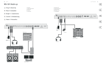
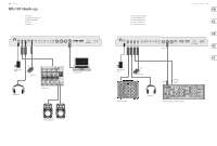
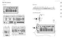
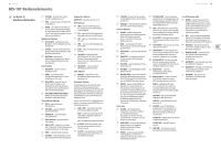
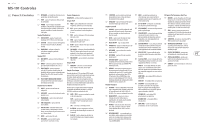
14 MS-101 MS-101 Controls (EN) Step 2: Controls (1) KEYBOARD - the keyboard has 32 semiweighted, full-size keys. (2) TUNE - adjust the frequency of the main VCO of the synthesizer. (3) POWER - turn the synthesizer on or off. Make sure all the connections are made before turning on the unit. The LED shows when power is applied and the unit is turned on. Modulator Section (4) LFO/CLK RATE - adjust the frequency of the modulation LFO. The LED blinks at the current rate. (5) LFO RATE - select the frequency range of the LFO rate fader from Low, Medium, or High. (6) WAVEFORM - select the waveform from triangular, square wave, random, or noise. VCO Section (7) MOD DEPTH - adjust the level of modulation of the VCO. (8) RANGE - select the overall frequency range (octave) of the VCO from 16', 8', 4', and 2'. (9) PULSE WIDTH - adjust the pulse width of the VCO when the pulse modulation source switch is set to Manual. For LFO and ENV, it adjusts the effect of the modulation. (10) PULSE WIDTH MODULATION SOURCE- select from LFO triangular waveform, Manual, or Envelope. Source Mixer Section (11) PULSE - adjust the level of the pulse waveform. (12) SAW WAVE - adjust the level of the sawtooth waveform. (13) TRIANGULAR - adjust the level of the triangular waveform. (14) SUB OSCILLATOR - adjust the level of the sub oscillator. (15) SUB OSC TYPE - select the type of sub oscillator, from 1 octave down, 2 octaves down, or a narrower pulse width at 2 octaves down. (16) NOISE - adjust the level of noise. (17) EXT AUDIO - adjust the level of incoming audio from an external source. Sequencer Section SEQUENCER - see details on page 16 and 36. VCF Section (18) FREQ - adjust the cutoff frequency of the VCF. Frequencies above the cutoff are attenuated. (19) RES - adjusts the amount of volume level boost (resonance) given at the cut-off frequency. (20) ENV - adjust the amount of effect the envelope has on the VCF. (21) MOD - adjust the amount of effect the modulation has on the VCF. (22) KYBD - adjust the amount of effect the keyboard has on the VCF. (23) FM SOURCE - select the source of FM modulation on the VCF from: pulse, sawtooth, 1 octave down square wave, 2 octaves down square wave, 2 octaves down pulse, and noise. (24) FM AMOUNT - adjust the effect of FM modulation on the VCF. VCA Section (25) ENV/GATE - select if the VCA is affected by the envelope controls, or by gate. Envelope Section When applied to the VCA, the ADSR envelope is used to control the level of the note being played over time. When applied to the VCF, the ADSR envelope is used to control the cut-off frequency of the filter for each note played over time. In addition, the ADSR envelope can also affect the VCO pulse width modulation. Note that the ATTACK, DECAY and RELEASE stages are measured in units of time, and the SUSTAIN stage is measured in units of level. (26) GATE + TRIG - a new envelope is triggered at each key press. GATE - when a new note is pressed, a new envelope is trigged after the current one is done. LFO - the envelope is triggered by the LFO. (27) A-ATTACK - this adjusts the time for the level to reach maximum after a key is pressed. (28) D-DECAY - this adjusts the time to decay down to the SUSTAIN level after the attack time is over. (29) S-SUSTAIN - this sets the sustain level reached after the attack and decay time are over. (30) R-RELEASE - this adjusts the time it takes for the signal to decay once the key is released. Quick Start Guide 15 Control Section (44) VCF CV INPUT - the VCF can be controlled by Live Performance Kit (31) VOLUME - adjust the volume level of the an external control voltage connected here. (52) BENDER - adjusts the frequency of the VCO main output and headphones output. Turn (45) EXT CLK INPUT - an external clock signal can and/or the cut-off frequency of the VCF. The this down before turning the power on, or be applied here. level of the effect depends on the setting of before putting on headphones. (46) CV/GATE INPUT - these inputs allow the (32) GLIDE - adjust the amount of Glide time connection of control voltage and gate signals (Portamento) between notes on the keyboard. from compatible external devices such as the VCO and VCF Bender faders. This control only increases the frequency. The main unit bender can also be used at the same time. (33) GLIDE ON/OFF - turn the GLIDE on or off. (34) TRANSPOSE - adjust the keyboard in one octave steps, from Low, Medium, and High. modular synthesizer equipment. (47) CV/GATE OUTPUT - these outputs allow the connection of control voltage and gate signals to compatible external devices such as (53) MOD - press and hold to add LFO modulation. The level of effect depends upon the setting of the LFO mod fader, and the other LFO controls. (54) CONNECTOR - fit into the GRIP and MOD (35) VCO FADER - adjust the effect of the bender modular synthesizer equipment. connectors in the main unit rear panel. controls on the VCO. (48) VELOCITY OUT - outputs a variable control (55) MOUNTING HOLES - fit the supplied screws (36) VCF FADER - adjust the effect of the bender voltage based on the key velocity. in these holes to secure the handle to the left controls on the VCF. (49) MIDI Connections - these 3 standard 5-pin side of the main unit. (37) LFO MOD FADER - adjust the amount of LFO DIN Jacks allow connections to other MIDI (56) STRAP POINT 1 - connect one end of the modulation added when the MOD switch equipment in your system. supplied strap here. on the grip is pressed, or the BENDER (38) is moved up. MIDI IN - receives MIDI data from an external (57) STRAP POINT 2 - secure this to the right side source. This will commonly be another MIDI of the main unit with the supplied screws. (38) BENDER - move left or right to adjust the frequency of the VCO and/or the cut-off frequency of the VCF. The level of the effect depends on the setting of the nearby VCO and VCF faders. Move it up to add LFO modulation. keyboard, an external hardware sequencer, a computer equipped with a MIDI interface, etc. MIDI THRU - passes through MIDI data received at the MIDI INPUT. (58) STRAP - the supplied strap attaches to the 2 strap points. The modulation effect depends upon the MIDI OUT - sends MIDI data to an application setting of the LFO MOD fader and other LFO controls. (50) USB PORT - This USB type B jack allows connection to a computer. The MS-101 will Rear Panel show up as a class-compliant USB MIDI device, (39) DC INPUT - connect the supplied DC capable of supporting MIDI in and out. power adapter here. The power adapter USB MIDI IN - accepts incoming MIDI data can be plugged into an AC outlet capable of from an application. supplying from 100V to 240V at 50 Hz/60 Hz. Use only the power adapter supplied. USB MIDI OUT - sends MIDI data to an application. (40) MAIN OUTPUT - connect this output to the line-level inputs of mixers, keyboard amplifiers, or powered speakers for example. (51) GRIP/ MOD - the connector of the live performance grip attaches here. (41) PHONES - connect your headphones to this output. Make sure the volume is turned down before putting on headphones. (42) EXT AUDIO INPUT - this input can be connected to the line level audio output from an external audio device. Adjust the level using the EXT AUDIO fader in the SOURCE MIXER section. (43) HOLD - an optional footswitch can be connected here, to hold or release any pattern playing in the Sequencer, and in normal performance.
-
 1
1 -
2
-
 3
3 -
 4
4 -
 5
5 -
 6
6 -
 7
7 -
 8
8 -
 9
9 -
 10
10 -
 11
11 -
 12
12 -
 13
13 -
14
-
15
-
16
-
17
-
18
-
19
-
20
-
21
-
22
-
23
 |
 |