Behringer RD-8 MKII User Manual - Page 13
Analog Filter
 |
View all Behringer RD-8 MKII manuals
Add to My Manuals
Save this manual to your list of manuals |
Page 13 highlights
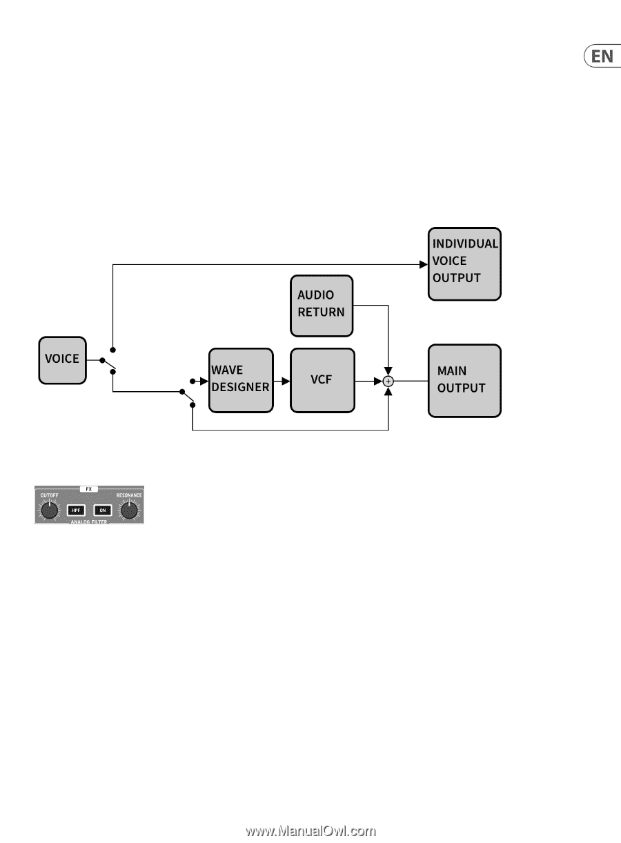
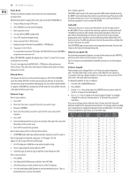
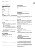
13 RD-8 MKII User Manual Filter section to be processed. The SIG LED shows that a signal is present in the Analog Filter/Wave Designer bus. The SEND button activates the Wave Designer circuit. How to assign voices to the FX bus: 1. Press SEND in the FX sections (flashes orange). 2. Use SELECT to assign which voices go to the bus (solid pink LED indicates voice sent to the FX bus). 3. Press SEND in the FX section to exit. SEND button will be solid white to show voices are assigned to the FX bus. TIP: Hold TAP/HOLD while pressing SEND to clear all voice from the FX bus. The diagram below shows the audio routing of the voices as they pass through the RD-8 MKII. Only one voice is shown in this example, but the same process applies to all voices. 10. Analog Filter The Analog Filter section works on selected sounds routed via an audio bus fed from the Wave Designer circuit. The CUTOFF control sets the frequency where the filter is applied. The filter cut off can be programmed and automated (when the ON button is flashing, automation is active). When the HPF (High Pass Filter) button is engaged the filter cuts the the low frequency cutoff point as you turn the control CW. When the HPF button is not engaged, the CUTOFF knob defaults to a lo-pass filter (LPF), which gradually cuts the high frequencies as you turn the control CCW. Press the ON button to activate the filter circuit. The RESONANCE control adjusts the resonance of the filter. Turning CW adds a peak at the cutoff frequency that accents the surrounding frequencies. The filter CUTOFF control setting can be recorded as automation. After programming a pattern, add the voice or voices you wish to be processed by the Analog Filter and Wave Designer bus as described earlier in this manual. Next, while the pattern is playing and in Record Mode, rotate the CUTOFF knob and listen to the results. Once you are happy with your filter sweep exit Record Mode. Next time you play the pattern, the recorded filter sweep will play back. Live Filter Mode can be toggled on and off, and this toggling action gives you either manual control of the filter frequency or automated Filter Mode, which uses the stored filter automation data. The live Filter Mode can be toggled on and off by holding the TAP/HOLD button and pressing the filter ON button to activate different states: • Flashing filter ON button= Filter plays stored automation data • Solid filter ON button = Filter in live control mode At any time, you can drop into Record Mode and adjust the filter settings that will be stored with the current pattern, as long as the filter settings are set to Pattern (see SETTINGS 11.5 below). It is also possible to manually program the filter per step or to edit a recorded filter sweep. 1. Press SETTINGS. 2. Press FILTER (STEP BUTTON 6). 3. Pressing different step keys (1-64) will display the current filter position from 0, turn the DATA control counter clockwise (CCW) to 255 turn clockwise (CW). Depending on which filter setting is in use, HPF or LPF, the filter will be fully open or closed. Up to 64 steps can be programmed using the keys in the LENGTH section to navigate step position. 4. Press SETTINGS twice to exit. 5. Save PATTERN. NOTE: Filter automation will now carry across when extending / copying lengths of patterns. - turning the Cut Off control in play mode will end playing the automated Filter mode. - turning the Cut Off knob in record with Filter on will start recording the automated Filter.
-
 1
1 -
2
-
3
-
4
-
5
-
6
-
7
-
 8
8 -
 9
9 -
 10
10 -
 11
11 -
 12
12 -
 13
13 -
 14
14 -
 15
15 -
 16
16 -
 17
17 -
 18
18 -
19
-
20
-
21
-
22
-
23
-
24
-
25
-
26
-
27
-
28
-
29
-
30
 |
 |