Belkin F1DC108H User Manual - Page 15
Connecting the Rack-Mount Console with Multiple, PRO3 KVM Switches Daisy-Chaining - sr
 |
View all Belkin F1DC108H manuals
Add to My Manuals
Save this manual to your list of manuals |
Page 15 highlights
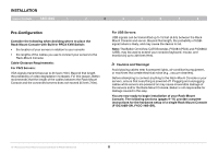
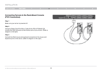
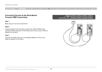
INSTALLATION Table of Contents sections 1 2 3 4 Connecting the Rack-Mount Console with Multiple PRO3 KVM Switches (Daisy-Chaining) You can daisy-chain up to 15 additional PRO3 KVM Switches (F1DA104Z, F1DA108Z, F1DA116Z, F1DA104Q, F1DA108Q, and F1DA116Q), allowing a server administrator to manage up to a maximum of 256 servers from one console. Each daisy-chained PRO3 KVM Switch is referred to as a "BANK" and is assigned an address. The Rack-Mount Console is BANK 00 and is referred to as the "primary" KVM switch. BANKs 01 through 15 are referred to as "secondary" KVM switches. Note: The Rack-Mount Console (F1DC108B-SR, F1DC116B-SR) must be designated as the primary KVM switch. Refer to the diagram on the right. Note: A Daisy-Chain Cable (F1D108-CBL) is required to daisy-chain each PRO3 KVM Switch and is available through your Belkin reseller, or online at www.belkin.com. cable 1 cable 2 cable 3 5 6 7 8 Primary unit (BANK 00) Secondary unit (BANK 01) Secondary unit (BANK 02) Secondary unit (BANK 03) 19" Widescreen Rack-Mount Console with Built-In PRO3 KVM Switch 13
-
 1
1 -
2
-
3
-
4
-
5
-
6
-
7
-
8
-
9
-
 10
10 -
 11
11 -
 12
12 -
 13
13 -
 14
14 -
 15
15 -
 16
16 -
 17
17 -
 18
18 -
 19
19 -
 20
20 -
21
-
22
-
23
-
24
-
25
-
26
-
27
-
28
-
29
-
30
-
31
-
32
-
33
-
34
-
35
-
36
-
37
-
38
-
39
-
40
-
41
-
42
-
43
 |
 |
