Beretta 92A1 Beretta 92A1 & 96A1 User Manual - Page 25
Reassembly
 |
View all Beretta 92A1 manuals
Add to My Manuals
Save this manual to your list of manuals |
Page 25 highlights
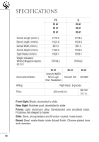
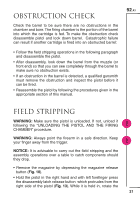
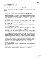
REASSEMBLY Assemble the pistol following the Field Strip procedure in reverse order. It is advisable to pay attention to the following points. 92 A1 • Engage the manual safety (Model FS only) (Fig. 6a / 6b). • When the barrel and locking block assembly are correctly inserted into the slide, they should rest securely inside the slide without movement. (The extractor must lie in its groove in the barrel). • The locking block lugs should rest firmly in their seats in the slide (the locking block plunger should protrude from the barrel) (Fig. 20). • Insert the recoil spring guide in its housing in the slide hole as shown in Fig. 21, 22 and 23. • The recoil spring guide head (flat part) should lodge in the center of its groove in the locking block (Fig. 24). • When the slide and barrel assembly are placed back on the frame, the slide/barrel assembly should be aligned with the frame or pushed beyond the rear of it (Fig. 25) to allow the disassembly latch to rotate and return to its original position (with the disassembly latch lever parallel to the slide). Please make sure that the disassembly latch lever is parallel to the slide. If not, by retracting the slide as indicated, manually rotate the disassembly latch to allow it to return to its original position. • Retract the slide to check the correct assembly operation. • Decock the hammer. - by operating the manual safety/hammer decocking lever (model FS) - by operating the hammer decocking lever (model G). The lever returns automatically to the ready to fire position. 23
-
 1
1 -
2
-
3
-
4
-
5
-
6
-
7
-
8
-
9
-
10
-
11
-
12
-
13
-
14
-
15
-
16
-
17
-
18
-
19
-
 20
20 -
 21
21 -
 22
22 -
 23
23 -
 24
24 -
 25
25 -
 26
26 -
 27
27 -
 28
28 -
 29
29 -
 30
30 -
31
-
32
-
33
-
34
-
35
-
36
-
37
-
38
-
39
-
40
-
41
-
42
-
43
-
44
-
45
-
46
-
47
-
48
-
49
-
50
-
51
-
52
-
53
-
54
-
55
-
56
-
57
-
58
-
59
-
60
-
61
-
62
-
63
-
64
-
65
-
66
-
67
-
68
-
69
-
70
-
71
-
72
-
73
-
74
-
75
-
76
-
77
-
78
-
79
-
80
-
81
-
82
-
83
-
84
-
85
-
86
-
87
-
88
 |
 |