Beretta 96A1 Beretta 92A1 & 96A1 User Manual - Page 24
Fig. 14, Fig. 15, Fig.16, Fig. 17, Fig. 18, Fig. 19, CAUTION
 |
View all Beretta 96A1 manuals
Add to My Manuals
Save this manual to your list of manuals |
Page 24 highlights
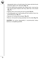
disassembly latch on the left side of the frame with the thumb clockwise approx. 90° downward (Fig. 14). • Pull the slide-barrel assembly with locking block, recoil spring and spring guide forwards until they slide free of the frame (Fig. 15). • Slightly press recoil spring and spring guide (Fig.16). • Lift spring guide and recoil spring unit and remove it from the barrel/slide group (Fig. 17). • Depress the locking block plunger (Fig. 18). • Remove the barrel's locking assembly from the slide (Fig. 19). CAUTION: No further disassembly is recommended unless done by a competent gunsmith. 22
-
 1
1 -
2
-
3
-
4
-
5
-
6
-
7
-
8
-
9
-
10
-
11
-
12
-
13
-
14
-
15
-
16
-
17
-
18
-
 19
19 -
 20
20 -
 21
21 -
 22
22 -
 23
23 -
 24
24 -
 25
25 -
 26
26 -
 27
27 -
 28
28 -
 29
29 -
30
-
31
-
32
-
33
-
34
-
35
-
36
-
37
-
38
-
39
-
40
-
41
-
42
-
43
-
44
-
45
-
46
-
47
-
48
-
49
-
50
-
51
-
52
-
53
-
54
-
55
-
56
-
57
-
58
-
59
-
60
-
61
-
62
-
63
-
64
-
65
-
66
-
67
-
68
-
69
-
70
-
71
-
72
-
73
-
74
-
75
-
76
-
77
-
78
-
79
-
80
-
81
-
82
-
83
-
84
-
85
-
86
-
87
-
88
 |
 |

22
disassembly latch on the left side of the frame with the thumb
clockwise approx. 90° downward (
Fig. 14
).
• Pull the slide-barrel assembly with locking block, recoil spring
and spring guide forwards until they slide free of the frame
(
Fig. 15
).
• Slightly press recoil spring and spring guide (
Fig.16
).
• Lift spring guide and
recoil spring unit and remove it from the
barrel/slide group (
Fig. 17
).
• Depress the locking block plunger (
Fig. 18
).
• Remove
the barrel’s locking assembly from the slide (
Fig. 19
).
CAUTION:
No further disassembly is recommended unless
done by a competent gunsmith.