Biostar 945GC MICRO 775 Setup Manual
Biostar 945GC MICRO 775 Manual
 |
View all Biostar 945GC MICRO 775 manuals
Add to My Manuals
Save this manual to your list of manuals |
Biostar 945GC MICRO 775 manual content summary:
- Biostar 945GC MICRO 775 | Setup Manual - Page 1
945GC-M7 SE / 945GC Micro 775 Setup Manual FCC Information and Copyright This equipment has been tested and found radio frequency energy and, if not installed and used in accordance with the instructions, may cause harmful interference to radio communications. There is no guarantee that interference - Biostar 945GC MICRO 775 | Setup Manual - Page 2
Rear Panel Connectors (for Ver 6.x 4 1.5 Rear Panel Connectors (for Ver 5.x 4 1.6 Motherboard Layout (for 945GC-M7 SE 5 1.7 Motherboard Layout (for 945GC Micro 775 6 Chapter 2: Hardware Installation 7 2.1 Installing Central Processing Unit (CPU 7 2.2 FAN Headers 9 2.3 Installing - Biostar 945GC MICRO 775 | Setup Manual - Page 3
945GC-M7 SE / 945GC Micro 775 CHAPTER 1: INTRODUCTION 1.1 BEFORE YOU START Thank you for choosing our product. Before you start installing the motherboard, please make sure you follow the instructions Rear I/O Panel for ATX Case X 1 User's Manual X 1 Fully Setup Driver CD X 1 Serial ATA Cable X 1 FDD - Biostar 945GC MICRO 775 | Setup Manual - Page 4
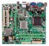
Motherboard Manual 1.3 MOTHERBOARD FEATURES 945GC-M7 SE 945GC Micro 775 LGA 775 LGA 775 Intel Core2Duo / Pentium 4 / Pentium D / Intel Core2Duo / Pentium 4 / Pentium D / Celeron D processor up to 3.8 GHz Celeron D processor up to 3.8 GHz *It is recommended to use processors with - Biostar 945GC MICRO 775 | Setup Manual - Page 5
VGA port x1 I/O LAN port x1 USB Port x4 Audio Jack (Ver 6.x) x3 Board Size 219 (W) x 235 (L) mm Windows 2000 / XP / VISTA OS Support Biostar Reserves the right to add or remove support for any OS with or without notice. 945GC Micro 775 bandwidth is for RTL 8110SC only) Half / Full duplex - Biostar 945GC MICRO 775 | Setup Manual - Page 6
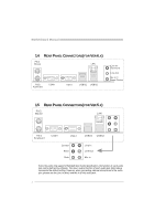
Mic In 1/ Bass/ Center 1.5 REAR PANEL CONNECTORS (FOR VER 5.X) PS/2 Mouse LAN PS/2 Keyboard COM1 VGA1 Center Rear Side USBX2 USBX2 Line In Line Out Mic In Since the audio chip supports High Definition Audio Specification, the function of each audio jack can be defined by software. The input - Biostar 945GC MICRO 775 | Setup Manual - Page 7
945GC-M7 SE / 945GC Micro 775 1.6 MOTHERBOARD LAYOUT (FOR 945GC-M7 SE) JKBMS1 JATXPWR2 LGA775 COJMC1OM1 CPU1 JVGA1 DDR2_A1 DDR2_B1 IDE1 FDD1 JPRNT1 JATXPWR1 JUSB2 JRJ45USB1 JCFAN1 Intel 945GC JAUDIOF1 JAUDIO1 Super I/O PEX16_1 Co dec PEX1_1 BIOS JCDIN1 LAN JSPDIF_OUT PCI1 PCI2 - Biostar 945GC MICRO 775 | Setup Manual - Page 8
Motherboard Manual 1.7 MOTHERBOARD LAYOUT (FOR 945GC MICRO 775) JKBMS1 JATXPWR2 JKBV1 LGA775 COJMC1OM1 CPU1 JVGA1 DDR2_A1 DDR2_B1 IDE1 FDD1 JPRNT1 JATXPWR1 JUSB2 JUSBV1 JRJ45USB1 JA UDI O2 (for Ver 5.x) AUD IO1 (for Ver 6.x) Super I/O JAUDI OF1 JCFAN1 Intel 945GC PE X1 6_ 1 Co de c - Biostar 945GC MICRO 775 | Setup Manual - Page 9
945GC-M7 SE / 945GC Micro 775 CHAPTER 2: HARDWARE INSTALLATION 2.1 INSTALLING CENTRAL PROCESSING UNIT (CPU) Special Notice: Remove Pin Cap before installation, and make good preservation for future use. When the CPU is removed, cover the Pin Cap on the empty socket to ensure pin legs won't be - Biostar 945GC MICRO 775 | Setup Manual - Page 10
Motherboard Manual Step 2: Look for the triangular cut edge on socket, and the golden dot on CPU should point forwards this triangular cut edge. The CPU will fit only in the correct orientation. Step 2-1: Step 2-2: Step 3: Hold the CPU down firmly, and then lower the lever to locked position to - Biostar 945GC MICRO 775 | Setup Manual - Page 11
945GC-M7 SE / 945GC Micro 775 2.2 FAN HEADERS These fan headers support cooling-fans built in the computer. The fan cable and connector may be different according to the fan manufacturer. Connect the fan cable to the connector while matching the black wire to pin#1. JCFAN1: CPU Fan Header JCFA N1 - Biostar 945GC MICRO 775 | Setup Manual - Page 12
Motherboard Manual 2.3 INSTALLING SYSTEM MEMORY A. DDR2 module DDR2_A1 DDR2_B1 1. Unlock a DIMM slot by pressing the retaining clips outward. Align a DIMM on the slot such that the notch - Biostar 945GC MICRO 775 | Setup Manual - Page 13
945GC-M7 SE / 945GC Micro 775 C. Dual Channel Memory installation To trigger the Dual Channel function of the motherboard, the memory module must meet the following requirements: Install memory module of the same density in pairs, shown in the following table. Dual Channel Status - Biostar 945GC MICRO 775 | Setup Manual - Page 14
Motherboard Manual 2.4 CONNECTORS AND SLOTS FDD1: Floppy Disk Connector The motherboard provides a standard floppy disk connector that supports 360K, 720K, 1.2M, 1.44M and 2.88M floppy disk types. This connector supports the provided floppy drive ribbon cables. 1 2 33 34 IDE1: Hard Disk - Biostar 945GC MICRO 775 | Setup Manual - Page 15
945GC-M7 SE / 945GC Micro 775 PEX16_1: PCI-Express x16 Slot - PCI-Express 1.0a compliant. - -Express supports a raw bit-rate of 2.5Gb/s on the data pins. - 2X bandwidth over the traditional PCI architecture. PEX1_1 PEX16_1 PCI1~PCI2: Peripheral Component Interconnect Slots The motherboard is - Biostar 945GC MICRO 775 | Setup Manual - Page 16
Motherboard Manual CHAPTER 3: HEADERS & JUMPERS SETUP 3.1 HOW TO SETUP JUMPERS The illustration shows how to set up jumpers. When the jumper cap is placed on pins, the - Biostar 945GC MICRO 775 | Setup Manual - Page 17
945GC-M7 SE / 945GC Micro 775 JATXPWR1: ATX Power Source Connector This connector allows user to connect 24-pin power connector on Power Source Connector By connecting this connector, it will provide +12V to CPU power circuit. 2 1 3 4 Pin Assignment 1 +12V 2 +12V 3 Ground 4 Ground 15 - Biostar 945GC MICRO 775 | Setup Manual - Page 18
Motherboard Manual JUSB3/JUSB4: Headers for USB 2.0 Ports at Front Panel This motherboard provides 2 USB 2.0 USB+ 6 USB+ 7 Ground 8 Ground 9 Key 10 NC SATA1~SATA4: Serial ATA Connectors The motherboard has a PCI to SATA Controller with 4 channels SATA interface, it satisfies the SATA 2.0 spec and - Biostar 945GC MICRO 775 | Setup Manual - Page 19
945GC-M7 SE / 945GC Micro 775 JSPDIF_OUT: Digital Audio out Connectors This connector allows user to connect the PCI bracket SPDIF output header. 13 Pin Assignment 1 +5V 2 SPDIF_OUT1 3 Ground JAUDIOF1: Front Panel Audio Header This header allows user to connect the front audio output cable - Biostar 945GC MICRO 775 | Setup Manual - Page 20
Motherboard Manual JCDIN1: CD-ROM Audio-in Connector This connector allows user to connect the audio source from the variaty devices, like CD-ROM, DVD-ROM, PCI sound to restore the BIOS safe setting and the CMOS data, please carefully follow the procedures to avoid damaging the motherboard. 3 1 Pin - Biostar 945GC MICRO 775 | Setup Manual - Page 21
945GC-M7 SE / 945GC Micro 775 JKBV1: Power Source Header for PS/2 Keyboard and Mouse (Only for 945GC Micro 775) 13 1 3 Pin 1-2 Close +5V for PS/2 keyboard and mouse. 1 3 Pin 2-3 close PS/2 keyboard and mouse are powered by +5V standby voltage. Note: In order to support this function "Power-on - Biostar 945GC MICRO 775 | Setup Manual - Page 22
Motherboard Manual JPRNT1: Printer Port Connector This header allows you to connector printer on the PC. 25 Pin Assignment 1 -Strobe 2 -ALF 3 Data 0 4 -Error 5 Data 1 6 -Init 7 Data 2 8 -Scltin 9 - Biostar 945GC MICRO 775 | Setup Manual - Page 23
945GC-M7 SE / 945GC Micro 775 CHAPTER 4: USEFUL HELP 4.1 DRIVER INSTALLATION NOTE After you installed your operating system, please insert the Fully Setup Driver CD into your optical drive and install the driver for better system performance. You will see the following window after you insert the CD - Biostar 945GC MICRO 775 | Setup Manual - Page 24
Motherboard Manual 4.2 AWARD BIOS BEEP CODE Beep Sound Meaning One long beep followed by two short Video card not found or video card beeps memory bad High-low siren sound CPU overheated System will shut down automatically One Short beep when system boot-up No error found during POST Long - Biostar 945GC MICRO 775 | Setup Manual - Page 25
945GC-M7 SE / 945GC Micro 775 B. CPU Overheated If the system shutdown automatically after power on system for seconds, that means the CPU protection function has been activated. When the CPU is over heated, the motherboard will shutdown automatically to avoid a damage of the CPU, and the system may - Biostar 945GC MICRO 775 | Setup Manual - Page 26
Motherboard Manual 4.4 TROUBLESHOOTING Probable Solution 1. No power to the system at all 1. Make sure power cable is Power light don't illuminate, fan securely plugged in. inside power supply does not turn 2. Replace cable. on. 3. Contact technical support. 2. Indicator light on keyboard - Biostar 945GC MICRO 775 | Setup Manual - Page 27
945GC-M7 SE / 945GC Micro 775 CHAPTER 5: WARPSPEEDER™ III 5.1 INTRODUCTION [WarpSpeeder™ III], a new powerful control utility, features three user-friendly functions including Overclock Manager, Overvoltage Manager, and Hardware Monitor. With the Overclock Manager, users can easily adjust the - Biostar 945GC MICRO 775 | Setup Manual - Page 28
Motherboard Manual 5.3 INSTALLATION 1. Execute the setup execution file, and then the following dialog will pop up. Please click "Next" "Finish" button. Usage: The following figures are only for reference, the screen printed in this user manual will change according to your motherboard on hand. 26 - Biostar 945GC MICRO 775 | Setup Manual - Page 29
™ III 945GC-M7 SE / 945GC Micro 775 1. Desktop Icon: After the [WarpSpeeder™ III] has been installed, a [WarpSpeeder™ III] icon will appear on the desktop, just like the icon shown below. Now you can launch the [WarpSpeeder™ III] utility simply by double-clicking the desktop icon. 2. Main Panel - Biostar 945GC MICRO 775 | Setup Manual - Page 30
Motherboard Manual 3. Overclock/Overvoltage Panel Click the Overclock/Overvoltage button in the Main Panel, the button will be highlighted and the Overclock/Overvoltage Panel will show up as the following figure. As you can see, the Overclock Panel is on the right side, and the Overvoltage Panel is - Biostar 945GC MICRO 775 | Setup Manual - Page 31
945GC-M7 SE / 945GC Micro 775 Overclock Panel contains these features: a. "Auto-Overclock": User can click this button and [ verified best and stable frequency. b. "Verify": If you use the "Manual Adjust" bar to adjust the CPU frequency, then you can click this button and [WarpSpeeder™ III] will - Biostar 945GC MICRO 775 | Setup Manual - Page 32
Motherboard Manual Overvoltage Panel contains these features: a. "CPU Voltage": This function allows user to adjust CPU voltage. Click on "+" to increase or "-" to decrease the CPU voltage. b. "Memory Voltage": This function allows user to adjust Memory voltage. Click on "+" to increase or "-" to - Biostar 945GC MICRO 775 | Setup Manual - Page 33
945GC-M7 SE / 945GC Micro 775 5. About Panel Click the "about" button in Main Panel, the button will be highlighted and the About Panel will show up as the following figure. In this panel, you can get model name and detail information in hints of all the chipset that are related to overclocking. You - Biostar 945GC MICRO 775 | Setup Manual - Page 34
Motherboard Manual APPENDENCIES: SPEC IN OTHER LANGUAGE GERMAN 945GC-M7 SE 945GC Micro 775 LGA 775 LGA 775 Intel Core2Duo / Pentium 4 / Pentium D / Intel Core2Duo / Pentium 4 / Pentium D / Celeron D Prozessoren mit bis zu 3,8 GHz Celeron D Prozessoren mit bis zu 3,8 GHz *It is recommended - Biostar 945GC MICRO 775 | Setup Manual - Page 35
945GC-M7 SE / 945GC Micro 775 945GC-M7 SE (Gigabit-Bandbreite nur beim RTL 8110SC) Halb-/ Vollduplex-Funktion 945GC Micro 775 (Gigabit-Bandbreite nur beim RTL 8110SC) Halb-/ Vollduplex-Funktion ALC662(VER 6.X) Audio-Codec 5.1-Kanal-Audioausgabe (VER 6.X) Unterstützt High-Definition Audio Steckpl - Biostar 945GC MICRO 775 | Setup Manual - Page 36
Motherboard Manual FRANCE 945GC-M7 SE 945GC Micro 775 LGA 775 LGA 775 Processeurs Intel Core2Duo / Pentium 4 / Processeurs Intel Core2Duo / Pentium 4 / Pentium D / Celeron D jusqu'à 3,8 GHz Pentium D / Celeron D jusqu'à 3,8 GHz *It is recommended to use processors with 95W *It - Biostar 945GC MICRO 775 | Setup Manual - Page 37
USB x4 Fiche audio (Ver 6.x) x3 Fiche audio (Ver 6.x) x3 Fiche audio (Ver 5.x) x6 Dimensions 219mm (l) X 235 mm (H) de la carte 219mm (l) X 235 mm (H) Windows 2000 / XP / VISTA Windows 2000 / XP / VISTA Support SE Biostar se réserve le droit d'ajouter ou de Biostar se réserve le droit - Biostar 945GC MICRO 775 | Setup Manual - Page 38
Motherboard Manual ITALIAN 945GC-M7 SE 945GC Micro 775 LGA 775 LGA 775 Processore Intel Core2Duo / Pentium 4 / Processore Intel Core2Duo / Pentium 4 / Pentium Velocità di trasferimento dei dati fino a 3 Gb/s. Gb/s. Compatibile specifiche SATA Versione 2.0. Compatibile specifiche SATA - Biostar 945GC MICRO 775 | Setup Manual - Page 39
945GC-M7 SE / 945GC Micro 775 945GC-M7 SE 945GC Micro 775 Codec audio ALC662(VER 6.X) Uscita audio 5.1 canali (VER 6.X) Supporto audio High-Definit ion (HD) ALC861VD(VER 6.X) / ALC888(VER 5.X) Uscita audio 5.1 canali (VER 6.X) Uscita audio 7.1 canali (VER 5.X) Supporto audio High-Definit ion ( - Biostar 945GC MICRO 775 | Setup Manual - Page 40
Motherboard Manual SPANISH 945GC-M7 SE 945GC Micro 775 LGA 775 Procesador Intel Core2Duo / Pentium 4 / LGA 775 Procesador Intel Core2Duo / Pentium 4 / Pentium D / Celeron D hasta 3,8 GHz Pentium D / Celeron D hasta 3,8 GHz *It is recommended to use processors with 95W *It is recommended to - Biostar 945GC MICRO 775 | Setup Manual - Page 41
945GC-M7 SE / 945GC Micro 775 945GC-M7 SE Códecs de sonido ALC662(VER 6.X) Salida de sonido de 5.1 canales (VER 6.X) Soporte de sonido Alta Definición 945GC Micro 775 ALC861VD(VER 6.X) / ALC888(VER 5.X) Salida de sonido de 5.1 canales (VER 6.X) Salida de sonido de 7.1 canales (VER 5.X) Soporte - Biostar 945GC MICRO 775 | Setup Manual - Page 42
Motherboard Manual PORTUGUESE 945GC-M7 SE 945GC Micro 775 LGA 775 LGA 775 Processador Intel Core2Duo / Pentium 4 / Processador Intel Gb/s. Velocidades de transmissão de dados até 3 Gb/s. Compatibilidade com a especificação SATA Compatibilidade com a especificação SATA versão 2.0. vers - Biostar 945GC MICRO 775 | Setup Manual - Page 43
945GC-M7 SE / 945GC Micro 775 Codec de som 945GC-M7 SE ALC662(VER 6.X) Saída de áudio de 5.1 canais (VER 6.X) Suporta a especificação High-Definition Audio 945GC Micro 775 ALC861VD(VER 6.X) / ALC888(VER 5.X) Saída de áudio de 5.1 canais (VER 6.X) Saída de áudio de 7.1 canais (VER 5.X) Suporta a - Biostar 945GC MICRO 775 | Setup Manual - Page 44
Motherboard Manual POLISH 945GC-M7 SE 945GC Micro 775 LGA 775 LGA 775 Procesor IntelCore2Duo / Pentium4 / PentiumD Procesor IntelCore2Duo / kontroler Serial ATA Transfer danych do 3 Gb/s. Zintegrowany kontroler Serial ATA Transfer danych do 3 Gb/s. Zgodność ze specyfikacją SATA w wersji - Biostar 945GC MICRO 775 | Setup Manual - Page 45
945GC-M7 SE / 945GC Micro 775 945GC-M7 SE 945GC Micro 775 Działanie w trybie połowicznego / pełnego dupleksu Działanie w trybie połowicznego / pełnego dupleksu Kodek dźwiękowy ALC662(VER 6.X) 5.1 kanałowe wyjście audio (VER 6.X) Obsługa High-Definition Audio ALC861VD(VER 6.X) / ALC888(VER - Biostar 945GC MICRO 775 | Setup Manual - Page 46
Motherboard Manual RUSSIAN 945GC-M7 SE 945GC Micro 775 LGA 775 Intel Core2Duo / Pentium 4 / LGA 775 Intel Core2Duo / Pentium 4 / Pentium D / Celeron D до 3.8 ГГц Pentium D / Celeron D до 3.8 ГГц CPU *It is recommended to use processors with 95W *It is recommended to use processors with 95W - Biostar 945GC MICRO 775 | Setup Manual - Page 47
945GC-M7 SE / 945GC Micro 775 945GC-M7 SE 945GC Micro 775 ALC662(VER 6.X) 5.1 VER 6.X High-Definition ALC861VD(VER 6.X) / ALC888(VER 5.X) 5.1 VER 6.X) 7.1 VER 5.X High-Definition Слот PCI Express x16 x1 Слот PCI Express x16 x1 Слоты Слот PCI Express x1 x1 Слот PCI - Biostar 945GC MICRO 775 | Setup Manual - Page 48
Motherboard Manual ARABIC 945GC Micro 775 945GC-M7 SE LGA 775 LGA 775 Intel Core2Duo / Pentium 4 / Pentium D Intel Core2Duo / Pentium 4 / Pentium D 3.8 Celeron D 3.8 Celeron D *It is recommended to use processors with 95W *It is recommended to use - Biostar 945GC MICRO 775 | Setup Manual - Page 49
945GC-M7 SE / 945GC Micro 775 945GC Micro 775 RTL 8110SC )ALC861VD(VER 6.X) / ALC888(VER 5.X ) (VER 6.X 5.1 ) (VER 5.X 7.1 3 Ver 6.x 219 235 X Windows 2000 / XP / VISTA Biostar Windows 2000 / XP / VISTA Biostar 47 - Biostar 945GC MICRO 775 | Setup Manual - Page 50
Motherboard Manual JAPANESE 945GC-M7 SE 945GC Micro 775 LGA 775 LGA 775 Intel Core2Duo / Pentium 4 / Pentium D / Intel Core2Duo / 33 / 66 / 100 PIO Mode 0~4 PIO Mode 0~4 SATA ATA 3 Gb SATA 2.0 ATA 3 Gb SATA 2.0 Realtek RTL 8100C / RTL 8110SC 10 / 100 / 1000 Mb - Biostar 945GC MICRO 775 | Setup Manual - Page 51
945GC-M7 SE / 945GC Micro 775 945GC-M7 SE PCI Express x16スロット x1 PCI Express x1スロット x1 PCIスロット x2 945GC Micro 775 7.1 VER 5.X PCI Express x16スロット x1 PCI Express x1スロット x1 PCIスロット x2 x1 x1 IDEコネクタ x1 IDEコネクタ x1 x1 x1 SATAコネクタ x4 SATAコネクタ x4 x1 - Biostar 945GC MICRO 775 | Setup Manual - Page 52
945GC-M7 SE / 945GC Micro 775 BIOS SETUP BIOS Setup 1 1 Main Menu...3 2 Standard CMOS Features 6 3 Advanced BIOS Features 8 4 Advanced Chipset Features 14 5 Integrated Peripherals 18 6 Power Management Setup 23 7 PnP/PCI Configurations 28 8 PC Health Status 30 9 Performance Booster Zone 32 - Biostar 945GC MICRO 775 | Setup Manual - Page 53
945GC-M7 SE / 945GC Micro 775 BIOS Setup Introduction This manual discussed Phoenix-Award™ Setup program built into the ROM BIOS. The Setup program allows users to modify the basic system configuration. This special information is then stored in battery-backed RAM so that it retains - Biostar 945GC MICRO 775 | Setup Manual - Page 54
-M7 SE / 945GC Micro 775 PCI Bus Support This PHOENIX-AWARD BIOS also supports Version 3.0 of the Intel PCI (Peripheral Component Interconnect) local bus specification. DRAM Support DDR2 SDRAM (Double Data Rate Two Synchronous DRAM) are supported. Supported CPUs This PHOENIX-AWARD BIOS supports the - Biostar 945GC MICRO 775 | Setup Manual - Page 55
945GC-M7 SE / 945GC Micro 775 1 Main Menu Once you enter Phoenix-Award BIOS™ CMOS Setup Utility, the Main Menu will appear on the screen. The Main Menu allows you to select from several setup functions. Use the arrow keys to select among the items and press to accept and enter - Biostar 945GC MICRO 775 | Setup Manual - Page 56
945GC-M7 SE / 945GC Micro 775 Integrated Peripherals This submenu allows you to configure certain IDE hard voltage and clock may cause the CPU or M/B damage!) Load Optimized Defaults This selection allows you to reload the BIOS when the system is having problems particularly with the boot sequence. - Biostar 945GC MICRO 775 | Setup Manual - Page 57
945GC-M7 SE / 945GC Micro 775 Set User Password If the Supervisor Password is not set, then the User Password will function in the all changes made during the current session and exit setup. message will be displayed before proceeding. confirmation Upgrade BIOS This submenu allows you to upgrade - Biostar 945GC MICRO 775 | Setup Manual - Page 58
945GC-M7 SE / 945GC Micro 775 2 Standard CMOS Features The items in Standard CMOS Setup value you want in each item. „ Figure 2. Standard CMOS Setup Main Menu Selections This table shows the selections that you can make on the Main Menu. Item Options Description Date mm : dd : yy Set the - Biostar 945GC MICRO 775 | Setup Manual - Page 59
945GC-M7 SE / 945GC Micro 775 Item Options Description IDE Channel 1 Master Options are in its in 2.88M, 3.5 in None Halt On All Errors Select the situation in which No Errors you want the BIOS to stop All, but Keyboard the POST process and All, but Diskette notify you. All, but Disk/ - Biostar 945GC MICRO 775 | Setup Manual - Page 60
945GC-M7 SE / 945GC Micro 775 3 Advanced BIOS Features „ Figure 3. Advanced BIOS Setup CPU FEATURE Delay Prior to Thermal Set this item to enable the CPU Thermal function to engage after the specified time. The Choices: 4 Min, 8 Min, 16 Min (default), 32 Min. 8 - Biostar 945GC MICRO 775 | Setup Manual - Page 61
945GC-M7 SE / 945GC Micro 775 Thermal Management This option allows you to choose the thermal management method of your monitor. The Choices: Thermal Monitor 1 (default), Thermal Monitor2. Notes: The choices will be different according to your CPU be "Disabled" for Win XP. The Choices: Disabled ( - Biostar 945GC MICRO 775 | Setup Manual - Page 62
945GC-M7 SE / 945GC Micro 775 Cache Setup CPU L3 Cache Depending on the CPU/chipset in use, you may be able to increase memory access time with this option. Enabled (default) Enable cache. Disab led Disable cache. Boot Seq & Floppy Setup This item allows you to setup Boot Seq & Floppy. 10 - Biostar 945GC MICRO 775 | Setup Manual - Page 63
945GC-M7 SE / 945GC Micro 775 Hard Disk Boot Priority These BIOS attempt to arrange the Hard Disk boot sequence , ZIP100, USB-FDD, USB-ZIP, USB-CDROM, LAN, Disabled. Boot Other Device When enabled, BIOS will try to load the operating system from other device when it failed to load from the three - Biostar 945GC MICRO 775 | Setup Manual - Page 64
-M7 SE / 945GC Micro 775 Report NO FDD for Win95 The Choices: NO (default), YES. Virus Warning This option allows you to choose the Virus Warning feature that is used to protect the IDE Hard Disk boot sector. If this function is enabled and an attempt is made to write to the boot sector, BIOS - Biostar 945GC MICRO 775 | Setup Manual - Page 65
945GC-M7 SE / 945GC Micro 775 Typematic Delay (Msec) Sets the delay time after the key is held down before it begins to repeat the keystroke. The Choices: 250 (default), 500, - Biostar 945GC MICRO 775 | Setup Manual - Page 66
945GC-M7 SE / 945GC Micro 775 4 Advanced Chipset Features This submenu allows you to configure the specific features of the chipset of CAS latency depends on the DRAM timing. The Choices: By SPD (default), Manual. CAS Latency Time When synchronous DRAM is installed, the number of clock cycles of - Biostar 945GC MICRO 775 | Setup Manual - Page 67
945GC-M7 SE / 945GC Micro 775 DRAM RAS# Precharge If an insufficient number of cycles is allowed for RAS to accumulate its charge before DRAM refresh, the refresh may be incomplete, - Biostar 945GC MICRO 775 | Setup Manual - Page 68
945GC-M7 SE / 945GC Micro 775 SLP S4# Assertion Width This item sets the minimum assertion width of the SLP-S4# signal to guarantee the DRAM has been safely power-cycled. The Choices: 4 to 5 Sec. (default), 3 to 4 Sec., 2 to 3 Sec., 1 to 2 Sec. System BIOS Cacheable Selecting Enabled allows you - Biostar 945GC MICRO 775 | Setup Manual - Page 69
945GC-M7 SE / 945GC Micro 775 PCI Express Root Port Func PCI Express Port 1 This item allows you to select the PCI Express Port. The Choices: Auto (default), Enabled, Disabled. PCI-E Compliancy Mode This item allows you to select the PCI-E Compliancy Mode. The Choices: v1.0a (default), v1.0. 17 - Biostar 945GC MICRO 775 | Setup Manual - Page 70
945GC-M7 SE / 945GC Micro 775 5 Integrated Peripherals „ Figure 5. Integrated Peripherals OnChip IDE Device If you highlight the literal "Press Enter" next to the "OnChip IDE Device" label and then press the enter key, it will take you a submenu with the following options: 18 - Biostar 945GC MICRO 775 | Setup Manual - Page 71
945GC-M7 SE / 945GC Micro 775 IDE HDD Block Mode Block mode is also called block transfer, multiple commands, or multiple sector read / write. If your IDE hard drive supports block mode (most new drives do), select Enabled for automatic detection of the optimal number of block mode (most new drives - Biostar 945GC MICRO 775 | Setup Manual - Page 72
945GC-M7 SE / 945GC Micro 775 SATA PORT Speed Settings The Choices: Disabled (default), Force GEN I, Force or disable EHCI controller only. This BIOS itself may/ may not have high speed USB support. If the BIOS has high speed USB support built in, the support will automatically turn on, when high - Biostar 945GC MICRO 775 | Setup Manual - Page 73
945GC-M7 SE / 945GC Micro 775 USB Mouse Support This item allows you to enable or disable the USB Mouse Legacy Support. Enabled Enable USB Mouse Support. Disabled (default) Disable USB Mouse Support. Onboard AC97 Audio This item allows you to decide to enable or disable to support AC97 Audio. - Biostar 945GC MICRO 775 | Setup Manual - Page 74
945GC-M7 SE / 945GC Micro 775 Onboard Parallel Port This item allows you to determine access onboard parallel port controller with which I/O Address. The Choices: 378/IRQ7 (default), 278/IRQ5, 3BC/ - Biostar 945GC MICRO 775 | Setup Manual - Page 75
945GC-M7 SE / 945GC Micro 775 6 Power Management Setup The Power Management Setup Menu allows you to configure your system to utilize energy conservation and power up/power down features. „ Figure 6. Power Management Setup ACPI & Wake Up Events 23 - Biostar 945GC MICRO 775 | Setup Manual - Page 76
945GC-M7 SE / 945GC Micro 775 ACPI Function This item displays BIOS to initialize the VGA card when system wakes up from S3 state. The system time is shortened if you disable the function, but system will need AGP driver to initialize the card. So, if the AGP driver of the VGA card does not support - Biostar 945GC MICRO 775 | Setup Manual - Page 77
945GC-M7 SE / 945GC Micro 775 POWER ON Function This item allows you to choose the power on function. The Choices: Button Only (default), Password, Hot Key, Mouse Move/Click, Mouse - Biostar 945GC MICRO 775 | Setup Manual - Page 78
945GC-M7 SE / 945GC Micro 775 Power Management This category allows you to select the type (or Suspend Mode = 1 hr. HDD Power Down = 15 min Max. Saving Maximum power management only available for sl CPU's. Suspend Mode = 1 min. HDD Power Down = 1 min. User Define Allows you to set each mode - Biostar 945GC MICRO 775 | Setup Manual - Page 79
945GC-M7 SE / 945GC Micro 775 Suspend Mode The item allows you to select the suspend type under ACPI state when the system has "hung." The Choices: Delay 4 Sec, Instant-Off (default). HPET Support This item allows you to enable or disable HPET. The Choices: Enabled (default), Disabled. HPET - Biostar 945GC MICRO 775 | Setup Manual - Page 80
945GC-M7 SE / 945GC Micro 775 7 PnP/PCI Configurations This section describes configuring the PCI bus system. PCI, or Personal Computer Interconnect, is a system which allows I/O devices to operate at speeds nearing the speed of the CPU itself uses when communicating with its own special components. - Biostar 945GC MICRO 775 | Setup Manual - Page 81
945GC-M7 SE / 945GC Micro 775 IRQ Resources This submenu will allow you to assign each you to configure the system interrupts. This is only configurable when "Resources Controlled By" is set to "Manual". IRQ-3 assigned to PCI Device IRQ-4 assigned to PCI Device IRQ-5 assigned to PCI Device IRQ-7 - Biostar 945GC MICRO 775 | Setup Manual - Page 82
945GC-M7 SE / 945GC Micro 775 8 PC Health Status „ Figure 8. PC Health Status CPU FAN Control The Choice "smart" can make your CPU FAN to reduce noise. The Choices: Smart (default), Always On. CPU Fan Off If the CPU Temperature is lower than the set value, FAN will turn off. The Choices: Min=0,. - Biostar 945GC MICRO 775 | Setup Manual - Page 83
945GC-M7 SE / 945GC Micro 775 SHUTDOWN TEMPERATURE This item allows you to set up the CPU shutdown Temperature. This item only effective under Windows 98 ACPI mode The Choices: 65OC/140OF, 70OC/149OF, 75OC/158OF, Disabled (default). SHOW H/W MONITOR IN POST - Biostar 945GC MICRO 775 | Setup Manual - Page 84
945GC-M7 SE / 945GC Micro 775 9 Performance Booster Zone „ Figure 9. Performance Booster Zone CPU Voltage This item allows you to select CPU Voltage Control. The Choices: StartUp (default), +0.012V~+0.787V. Memory Voltage The Choices:1.80V (default), 1.90V, 2.00V, 2.10V, 2.20V, 2.30V, 2.40V, 2.50V. - Biostar 945GC MICRO 775 | Setup Manual - Page 85
945GC-M7 SE / 945GC Micro 775 PCIE Clock select The Choices: Fixed 100 (default), Upto CPU, Manual PCIE Clock Display the PCIE Clock frequency; Min=100, Max=200, key in a DEC number. This option is configurable only when "PCIE Clock Select" is set to "Manual". PCI Clock The Choices: 33.33 (default)
-
 1
1 -
 2
2 -
 3
3 -
 4
4 -
 5
5 -
 6
6 -
 7
7 -
8
-
9
-
10
-
11
-
12
-
13
-
14
-
15
-
16
-
17
-
18
-
19
-
20
-
21
-
22
-
23
-
24
-
25
-
26
-
27
-
28
-
29
-
30
-
31
-
32
-
33
-
34
-
35
-
36
-
37
-
38
-
39
-
40
-
41
-
42
-
43
-
44
-
45
-
46
-
47
-
48
-
49
-
50
-
51
-
52
-
53
-
54
-
55
-
56
-
57
-
58
-
59
-
60
-
61
-
62
-
63
-
64
-
65
-
66
-
67
-
68
-
69
-
70
-
71
-
72
-
73
-
74
-
75
-
76
-
77
-
78
-
79
-
80
-
81
-
82
-
83
-
84
-
85
 |
 |

945GC-M7 SE / 945GC Micro 775
Setup Manual
FCC Information and Copyright
This equipment has been tested and found to comply with the limits of a Class
B digital device, pursuant to Part 15 of the FCC Rules. These limits are designed
to provide reasonable protection against harmful interference in a residential
installation. This equipment generates, uses and can radiate radio frequency
energy and, if not installed and used in accordance with the instructions, may
cause harmful interference to radio communications. There is no guarantee
that interference will not occur in a particular installation.
The vendor makes no representations or warranties with respect to the
contents here and specially disclaims any implied warranties of merchantability
or fitness for any purpose. Further the vendor reserves the right to revise this
publication and to make changes to the contents here without obligation to
notify any party beforehand.
Duplication of this publication, in part or in whole, is not allowed without first
obtaining the vendor’s approval in writing.
The content of this user’s manual is subject to be changed without notice and
we will not be responsible for any mistakes found in this user’s manual. All the
brand and product names are trademarks of their respective companies.