Biostar K8NHA GRAND K8NHA Grand user's manual - Page 12
Headers & Jumpers Setup
 |
View all Biostar K8NHA GRAND manuals
Add to My Manuals
Save this manual to your list of manuals |
Page 12 highlights
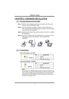
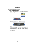
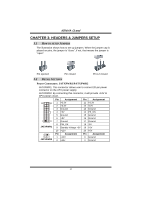
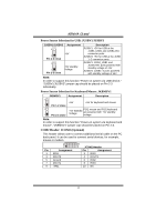
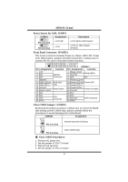
K8NHA Grand CHAPTER 3: HEADERS & JUMPERS SETUP 3.1 HOW TO SETUP JUMPERS The illustration shows how to set up jumpers. When the jumper cap is placed on pins, the jumper is "close", if not, that means the jumper is "open". Pin opened Pin closed Pin1-2 closed 3.2 DETAIL SETTINGS Power Connectors: JATXPWR1/PATXPWR2 JATXPWR1: This connector allows user to connect 20-pin power connector on the ATX power supply. JATXPWR2: By connecting this connector, it will provide +12V to CPU power circuit. Pin Assignment Pin Assignment 10 20 1 +3.3V 2 +3.3V 11 +3.3V 12 -12V 3 Ground 13 Ground 4 +5V 14 PS_ON 1 11 JATXPWR1 5 Ground 15 Ground 6 +5V 16 Ground 7 Ground 17 Ground 8 PW_OK 18 -5V 9 Standby Voltage +5V 19 +5V 10 +12V 20 +5V 2 1 3 JATXPWR2 Pin Assignment 1 +12V 2 +12v Pin Assignment 3 Ground 4 Ground 12
-
 1
1 -
2
-
3
-
4
-
5
-
6
-
 7
7 -
 8
8 -
 9
9 -
 10
10 -
 11
11 -
 12
12 -
 13
13 -
 14
14 -
 15
15 -
 16
16 -
 17
17 -
18
-
19
-
20
-
21
-
22
-
23
-
24
-
25
-
26
-
27
-
28
-
29
-
30
-
31
-
32
 |
 |
