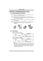
Biostar K8NHA GRAND K8NHA Grand user's manual - Page 14
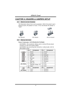
Front Panel Audio Out Header: JAUDIO1, CD-ROM Audio-in Header: JCDIN1, Digital Audio Out Connector:
 |
View all Biostar K8NHA GRAND manuals
Add to My Manuals
Save this manual to your list of manuals |
Page 14 highlights
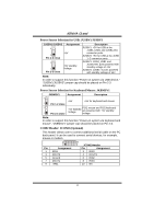
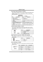
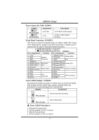
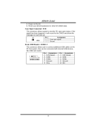
K8NHA Grand Front Panel Audio Out Header: JAUDIO1 This connector will allow user to connect with the front audio out put headers on the PC case. It will disable the output on back panel audio connectors. 2 1 Pin Assignment 1 Mic in/center 3 Mic power/Bass 5 Right line out/Speaker out Right 7 Reserved 9 Left line out/Speaker out Left 11 Right line in/Rear speaker Right 13 Left line in/Rear speaker Left 14 13 JAUDIO1 Pin Assignment 2 Ground 4 Audio power 6 Right line out/Speaker out Right 8 Key 10 Left line out/Speaker out Left 12 Right line in/Rear speaker Right 14 Left line in/Rear speaker Left CD-ROM Audio-in Header: JCDIN1 This connector allows user to connect the audio source from the veriaty devices, like CD-ROM, DVD-ROM, PCI sound card, PCI TV turner card etc.. Pin Assignment 1 1 Left channel input 2 Ground JCDIN1 3 Ground 4 Right channel input Digital Audio Out Connector: JSPDIF_OUT (optional) This connector will allow user to connect the PCI bracket SPDIF output header. 1 JSPDIF_OUT Pin Assignment 1 +5V 2 SPDIF OUT 3 Ground Front 1394 Header: J1394A1 This connector allows user to connect the front 1394 port for digital image devices. 2 10 1 9 J1394A1 Pin Assignment Pin Assignment 1 A+ 2 A- 3 Ground 4 Ground 5 B+ 6 B- 7 +12v 8 +12V 9 Key 10 Ground 14
-
 1
1 -
2
-
3
-
4
-
5
-
6
-
7
-
8
-
 9
9 -
 10
10 -
 11
11 -
 12
12 -
 13
13 -
 14
14 -
 15
15 -
 16
16 -
 17
17 -
 18
18 -
 19
19 -
20
-
21
-
22
-
23
-
24
-
25
-
26
-
27
-
28
-
29
-
30
-
31
-
32
 |
 |
