Biostar K8NHA GRAND K8NHA Grand user's manual - Page 15
Power Source for 1394: J1394V1, Front Panel Connector: JPANEL1, Close CMOS Jumper: JCMOS1, Clear - m grand bios
 |
View all Biostar K8NHA GRAND manuals
Add to My Manuals
Save this manual to your list of manuals |
Page 15 highlights
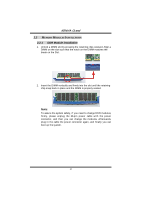
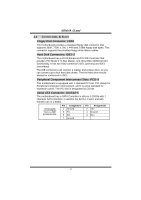
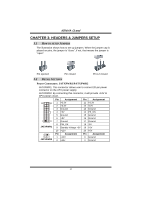
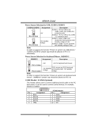
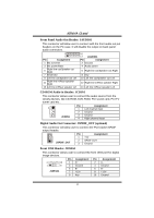
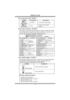
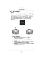
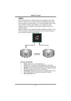
K8NHA Grand Power Source for 1394: J1394V1 J1394V1 1 3 Pin 1-2 close Assignment +3.3V SB 1 3 Pin 2-3 close +3.3V Description +3.3V SB for 1394 chipset. +3.3V for 1394 chipset. (Default) Front Panel Connector: JPANEL1 This 24-pin connector includes Power-on, Reset, HDD LED, Power LED, Sleep button, speaker and IrDA Connection. It allows user to connect the PC case's front panel switch functions. 2 1 Pin Assignment Function 1 +5V 3 N/A 5 N/A Speaker Connector 7 Speaker 9 HDD LED (+) Hard drive 11 HEE LED (-) LED 13 Ground Reset button 15 Reset control 17 N/A 19 N/A 21 +5V 23 IRTX IrDA Connector 24 23 JPANEL1 Pin Assignment Function 2 Sleep control Sleep button 4 Ground 6 N/A N/A 8 Power LED (+) 10 Power LED (+) Power LED 12 Power LED (-) 14 Power button Power-on button 16 Ground 18 Key 20 Key 22 Ground IrDA Connector 24 IRRX Close CMOS Jumper: JCMOS1 By placing the jumper on pin2-3, it allows user to restore the BIOS safe setting and the CMOS data, please carefully follow the procedures to avoid damaging the motherboard. JCMOS1 Assignment 3 1 Pin 1-2 close Normal Operation (Default). 3 1 Pin 2-3 close Clear CMOS data. ※ Clear CMOS Procedures: 1. Remove AC power line. 2. Set the jumper to "Pin 2-3 close". 3. Wait for five seconds. 4. Set the jumper to "Pin 1-2 close". 15
-
 1
1 -
2
-
3
-
4
-
5
-
6
-
7
-
8
-
9
-
 10
10 -
 11
11 -
 12
12 -
 13
13 -
 14
14 -
 15
15 -
 16
16 -
 17
17 -
 18
18 -
 19
19 -
 20
20 -
21
-
22
-
23
-
24
-
25
-
26
-
27
-
28
-
29
-
30
-
31
-
32
 |
 |
