Biostar M6VLA M6VLA user's manual - Page 18
Connectivity
 |
View all Biostar M6VLA manuals
Add to My Manuals
Save this manual to your list of manuals |
Page 18 highlights
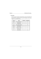
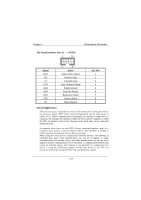
Chapter 1 Motherboard Description Connectivity The many ways that a serial port can be used make it necessary to be familiar with the pinout diagram. The following chart gives you the function of each pin on the 9-pin connector. This information can be used when configuring certain software programs to work with the serial port. Signal DCD RX TX DTR GND DSR RTS CTS RI Name Data Carrier Detect Receive Data Transmit Data Data Terminal Ready Signal Ground Data Set Ready Request to Send Clear to Send Ring Indicator DB9 PIN 1 2 3 4 5 6 7 8 9 DB25 PIN 8 3 2 20 7 6 4 5 22 1-14
-
 1
1 -
2
-
3
-
4
-
5
-
6
-
7
-
8
-
9
-
10
-
11
-
12
-
 13
13 -
 14
14 -
 15
15 -
 16
16 -
 17
17 -
 18
18 -
 19
19 -
 20
20 -
 21
21 -
 22
22 -
 23
23 -
24
-
25
-
26
-
27
-
28
-
29
-
30
-
31
-
32
-
33
-
34
-
35
-
36
-
37
-
38
-
39
-
40
-
41
-
42
-
43
-
44
-
45
-
46
-
47
-
48
-
49
-
50
-
51
-
52
-
53
-
54
-
55
-
56
-
57
-
58
-
59
-
60
-
61
-
62
-
63
-
64
-
65
-
66
-
67
-
68
-
69
-
70
-
71
-
72
-
73
-
74
-
75
-
76
 |
 |

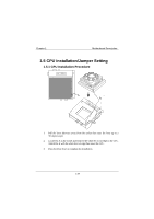
Chapter 1
Motherboard Description
1-14
Connectivity
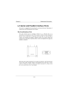
The many ways that a serial port can be used make it necessary to be familiar with
the pinout diagram. The following chart gives you the function of each pin on the
9-pin connector. This information can be used when configuring certain software
programs to work with the serial port.
Signal
Name
DB9 PIN
DB25 PIN
DCD
Data Carrier Detect
1
8
RX
Receive Data
2
3
TX
Transmit Data
3
2
DTR
Data Terminal Ready
4
20
GND
Signal Ground
5
7
DSR
Data Set Ready
6
6
RTS
Request to Send
7
4
CTS
Clear to Send
8
5
RI
Ring Indicator
9
22