Bosch HBL8753UC Installation Instructions - Page 6
Bosch Combination Ovens, Before you Begin
 |
View all Bosch HBL8753UC manuals
Add to My Manuals
Save this manual to your list of manuals |
Page 6 highlights
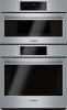
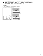
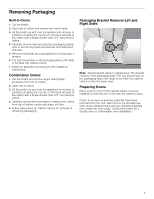
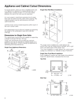
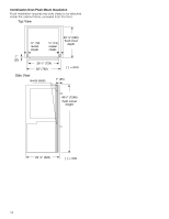
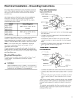
Bosch Combination Ovens The HBL8743UC, HBL8753UC and HBL87M53UC Bosch combination ovens are sold as sets, each of which includes two built-in oven components: a conventional wall oven (lower oven) and either a built-in speed oven or a microwave oven(upper oven). ▯ For ease of installation and improved alignment, the oven components are assembled together in the customer's home rather than at the factory. ▯ Each of the components are packed in separate boxes, which are strapped together prior to shipping. ▯ The combination ovens listed here are approved for use in a single cutout, using single power connection. ▯ Each conventional oven component is designed with an oven-mounted junction box on top, which is used for connecting the upper oven power cable. ▯ The hardware required for mounting the speed oven on top of the conventional oven will be found inside the conventional oven box. ▯ Each of the oven components has its own rating label, the component model number, FD number, etc. Before you Begin Tools and Parts Needed ▯ Phillips-head screwdriver ▯ Star-head screwdriver (T20) ▯ Measuring tape ▯ Drill with bit (1/8") ▯ Gloves ▯ Utility Knife Parts Included Phillips head screws (6). Power Requirements and Grounding The outlet must be properly grounded in accordance with all applicable codes. For Best Installation The oven can be difficult for two people to handle during installation. It is recommended that three or more people be available to assist with lifting the unit into place. Removal of the oven door (to reduce the unit weight and to provide necessary gripping points) can be cumbersome unless the detailed door removal instructions are followed carefully. Do not attempt to remove the speed oven door. Please take time to read and follow the instructions provided for an improved installation experience. Checklist Use this checklist to verify that you have completed each step of the installation process. This can help you avoid mistakes. ▯ Before installing the oven, be sure to verify the cabinet dimensions are correct and the required electrical connections are present. ▯ Refer to additional information in this manual regarding Safety, Cabinet Dimensions, Removing Packaging, Electrical Installation, Testing the Installation and Customer Service. ▯ Remove the lower oven door to reduce the unit weight and to provide access to gripping points for lifting. See "Remove Lower Oven Door Prior to Installation" information. ▯ Move the oven units into place in front of the cabinet opening, leaving the bottom packaging on the units to avoid damaging flooring. ▯ Remove the Star-head screws (T-20 size using Starhead screwdriver) holding the speed microwave oven to the base of its carton. ▯ Assemble the two units of the combination oven. See "Pre-Assembly of the Combination Oven". ▯ Connect the power cable from the lower oven to the junction box in the cabinet. ▯ Remove the Star-head screws (T-20 size using Starhead screwdriver) holding the lower oven to the base of its carton. ▯ Team-lift the unit directly into the cabinet cutout taking care not to pinch fingers, scratch arms or hands. ▯ Slide the unit all the way into place. ▯ Fasten the unit to the cabinet opening with the screws supplied using a Philips screwdriver. ▯ Reinstall the oven door removed in Step 3 above. ▯ Consult the complete installation instructions and follow the remainder of the procedures listed, including performing operation test. ▯ INSTALLER- Leave the literature pack and the accessories with the customer. 6
-
 1
1 -
 2
2 -
 3
3 -
 4
4 -
 5
5 -
 6
6 -
 7
7 -
 8
8 -
 9
9 -
 10
10 -
 11
11 -
 12
12 -
13
-
14
-
15
-
16
-
17
-
18
-
19
-
20
-
21
-
22
-
23
-
24
-
25
-
26
-
27
-
28
-
29
-
30
-
31
-
32
-
33
-
34
-
35
-
36
-
37
-
38
-
39
-
40
-
41
-
42
-
43
-
44
-
45
-
46
-
47
-
48
-
49
-
50
-
51
-
52
 |
 |