Bose Aviation Headset X Owner's guide - Page 15
Mounting the connector, CAUTION
 |
View all Bose Aviation Headset X manuals
Add to My Manuals
Save this manual to your list of manuals |
Page 15 highlights
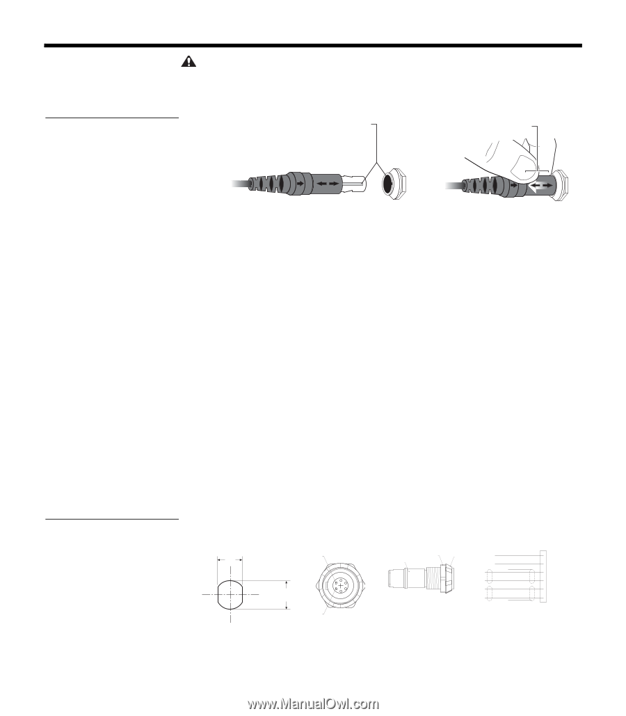
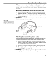
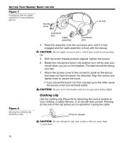
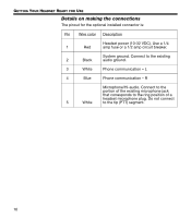
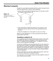
Figure 11 Attaching and removing the cable GETTING YOUR HEADSET READY FOR USE CAUTION: Do not attempt to pull the connector out without first pulling back on the sleeve. Forcing the connector out will cause damage to the cable and/or your aircraft instrument panel. Align keyway Slide sleeve to release Figure 12 Harness connector and schematic Mounting the connector Mount the connector into a cutout, as shown in Figure 12 below. Connect the eight wires as follows: • Two for the microphone • Two for audio • One for power • One for ground • Two for audio shields Audio and microphone wires should be connected to the back of the existing microphone and headphone jacks, leaving existing jacks intact for use with conventional headsets. This is usually the fastest installation method (see Figures 1 - 4 for reference). Audio shields should be connected to ground at the existing jack. (Caution: Use of two headsets wired in parallel is not advised. This may result in reduced performance.) Panel Hole Required Receptacle Pinout (Front View) Receptacle Backnut (Side View) Aircraft Interface Schematic 12.5mm .49" Pin 6 14.0mm .55" Pin 1 Backnut M14 X 1 Hex Nut Front Nut RED BLK WHT BLK/WH BLU WHT WH/BLU BLK/WH • 1 V+IN • 2 GND • 3 COMM L • 4 COMM R • 5 MIC HI • 6 MIC LO 15
-
 1
1 -
2
-
3
-
4
-
5
-
6
-
7
-
8
-
9
-
 10
10 -
 11
11 -
 12
12 -
 13
13 -
 14
14 -
 15
15 -
 16
16 -
 17
17 -
 18
18 -
 19
19 -
 20
20 -
21
-
22
-
23
-
24
-
25
-
26
-
27
-
28
-
29
-
30
-
31
-
32
-
33
-
34
-
35
-
36
 |
 |