Bose Aviation Headset X Owner's guide - Page 18
Barrel ground gnd refers to aircraft grounds - for helicopters
 |
View all Bose Aviation Headset X manuals
Add to My Manuals
Save this manual to your list of manuals |
Page 18 highlights
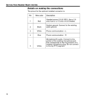
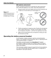
GETTING YOUR HEADSET READY FOR USE Figure 13 Diagram of connections for a mono signal Mono, stereo, and helicopter connection diagrams 10-32 V DC 1/2A RED BLK WHT BLK/WH BLU WHT WHT/BLU BLK/WH Microphone - Jack 1V+IN 2 GND 3 COMM L 4 COMM R 5 MIC HI 6 MIC LO Ring (audio) Existing wiring to aircraft intercom/ audio panel TPP (PTT) Barrel (gnd) Headphone - Jack Exisiting PTT switch and wiring (no connection to Bose headset) Tip (phone audio) Barrel (audio gnd) Figure 14 Diagram of connections to aircraft stereo jacks 10-32 V DC 1/2A RED BLK WHT BLU WHT WHT/BLU BLK/WH BLK/WH Microphone - Jack 1V+IN 2 GND 3 COMM L 4 COMM R 5 MIC HI 6 MIC LO Audio Existing wiring to aircraft stereo intercom/audio panel TPP (PTT) Phone audio (right) Barrel (gnd) Stereo Headphone - Jack Exisiting PTT switch and wiring (no connection to Bose headset) Tip (phone audio left) Barrel (audio gnd) Figure 15 Diagram of connections to a helicopter single jack Existing wiring to helicopter intercom/ audio panel WHT/BLU 6 MIC LO WHT 5 MIC HI BLU 4 COMM R WHT 3 COMM L BLK 10-32 RED V DC 1/2A 2 1 GND V+IN Existing single 4prong jack Barrel (audio gnd) Note: Barrel ground (gnd) refers to aircraft grounds 18
-
 1
1 -
2
-
3
-
4
-
5
-
6
-
7
-
8
-
9
-
10
-
11
-
12
-
 13
13 -
 14
14 -
 15
15 -
 16
16 -
 17
17 -
 18
18 -
 19
19 -
 20
20 -
 21
21 -
 22
22 -
 23
23 -
24
-
25
-
26
-
27
-
28
-
29
-
30
-
31
-
32
-
33
-
34
-
35
-
36
 |
 |
