Bose Aviation Headset X Owner's guide - Page 17
VTCS-6 Vibratite, Notes, Adhesives approved for use with this connector are
 |
View all Bose Aviation Headset X manuals
Add to My Manuals
Save this manual to your list of manuals |
Page 17 highlights
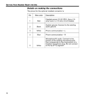
GETTING YOUR HEADSET READY FOR USE Notes • For use with a stereo intercom, connect the left and right channels to their respective positions. If your intercom provides a monaural audio signal, connect pins 3 & 4 together to the tip of the existing phone jack. • Do not use excessive force or bend the installed connector. This may damage or break internal solder joints. • If the boom microphone works on radio transmit but not through the intercom, check pin 6. It may be incorrectly wired to the PTT segment of the microphone jack. • The wires connecting pins 3 & 4 and pins 5 & 6 are shielded, twisted pairs with a shield termination exiting with a black/white wire for each pair. Connect shields to existing audio wiring shields or to audio ground, if existing wiring is not shielded. • The Bose aircraft panel connector cannot be installed to an audio system using transformer-coupled audio outputs. Call the Bose Aviation Headset Department for details: 800-287-0611. • Connecting power directly to pins 5 or 6 will result in damage to the microphone. • The wire guage is 22 AWG. Adhesives approved for use with this connector are: • VTCS-6 Vibratite • Three Bond 1401 Do not let cyanoacrylate-based adhesives, flux remover, or other caustic compounds contact the connector body. These chemicals cause irreparable damage to the connector. 17
-
 1
1 -
2
-
3
-
4
-
5
-
6
-
7
-
8
-
9
-
10
-
11
-
 12
12 -
 13
13 -
 14
14 -
 15
15 -
 16
16 -
 17
17 -
 18
18 -
 19
19 -
 20
20 -
 21
21 -
 22
22 -
23
-
24
-
25
-
26
-
27
-
28
-
29
-
30
-
31
-
32
-
33
-
34
-
35
-
36
 |
 |