Bose Aviation Headset X Owner's guide - Page 16
Details on making the connections, Microphone/Hi-audio. Connect to
 |
View all Bose Aviation Headset X manuals
Add to My Manuals
Save this manual to your list of manuals |
Page 16 highlights
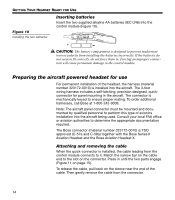
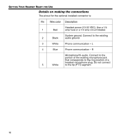
GETTING YOUR HEADSET READY FOR USE Details on making the connections The pinout for the optional installed connector is: Pin Wire color Description Headset power (10-32 VDC). Use a 1/4 1 Red amp fuse or a 1/2 amp circuit breaker. System ground. Connect to the existing 2 Black audio ground. 3 White Phone communication - L 4 Blue Phone communication - R Microphone/Hi-audio. Connect to the portion of the existing microphone jack that corresponds to the ring position of a headset microphone plug. Do not connect 5 White to the tip (PTT) segment. 16
-
 1
1 -
2
-
3
-
4
-
5
-
6
-
7
-
8
-
9
-
10
-
 11
11 -
 12
12 -
 13
13 -
 14
14 -
 15
15 -
 16
16 -
 17
17 -
 18
18 -
 19
19 -
 20
20 -
 21
21 -
22
-
23
-
24
-
25
-
26
-
27
-
28
-
29
-
30
-
31
-
32
-
33
-
34
-
35
-
36
 |
 |

16
G
ETTING
Y
OUR
H
EADSET
R
EADY
FOR
U
SE
Details on making the connections
The pinout for the optional installed connector is:
Pin
Wire color
Description
1
Red
Headset power (10-32 VDC). Use a 1/4
amp fuse or a 1/2 amp circuit breaker.
2
Black
System ground. Connect to the existing
audio ground.
3
White
Phone communication – L
4
Blue
Phone communication – R
5
White
Microphone/Hi-audio. Connect to the
portion of the existing microphone jack
that corresponds to the ring position of a
headset microphone plug. Do not connect
to the tip (PTT) segment.