Boss Audio BV7330 User Manual in English - Page 7
Installation - wiring harness
 |
View all Boss Audio BV7330 manuals
Add to My Manuals
Save this manual to your list of manuals |
Page 7 highlights
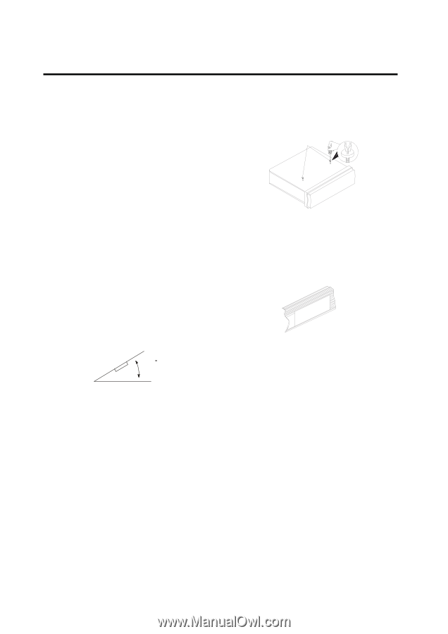
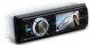
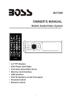
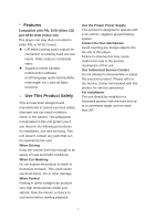
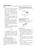
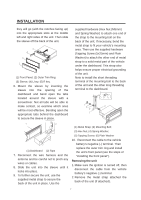
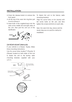
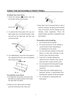
INSTALLATION Notes: y Choose the mounting location where the unit will not interfere with the normal driving function of the driver. y Before finally installing the unit, connect the wiring temporarily and make sure it is all connected up properly and the unit and the system work properly. y Use only the parts included with the unit to ensure proper installation. The use of unauthorized parts can cause malfunctions. y Consult with your nearest dealer if installation requires the drilling of holes or other modifications of the vehicle. y Install the unit where it does not get in the driver's way and cannot injure the passenger. y If installation angel exceeds 30°from horizontal, the unit might not give its optimum performance. 30 y Avoid installing the unit where it would be subject to high temperature, such as from direct sunlight, or from hot air, from the heater, or where it would be subject to dust, dirt or excessive vibration. DIN FRONT/REAR-MOUNT This unit can be properly installed either from "Front" (conventional DIN Front-mount) or "Rear" (DIN Rear-mount installation, utilizing threaded screw holes at the sides of the unit chassis). For details, refer to the following illustrated installation methods. TAKE OUT SCREW BEFORE INSTALLATION Before Installing the unit, please remove the two screws. Take out screw before installation. DIN FRONT-MOUNT (Method A) Installation Opening This unit can be installed in any dashboard having an opening as shown below: Installing the unit Be sure you test all connections first, and then follow these steps to install the unit. 1. Make sure the ignition is turned off, and then disconnect the cable from the vehicle battery's negative (-) terminal. 2. Disconnect the wire harness and the antenna. 3. Press the release button on the front panel and remove the control panel (see the steps of "removing the front panel"). 4. Lift the top of the outer trim ring then pull it out to remove it. 5. The two supplied keys release tabs inside the unit's sleeve so you can remove it. Insert the keys as far as 6
-
 1
1 -
 2
2 -
 3
3 -
 4
4 -
 5
5 -
 6
6 -
 7
7 -
 8
8 -
 9
9 -
 10
10 -
 11
11 -
 12
12 -
13
-
14
-
15
-
16
-
17
-
18
-
19
-
20
-
21
-
22
-
23
-
24
-
25
-
26
-
27
 |
 |