Bowflex Sport Assembly Manual
Bowflex Sport Manual
 |
View all Bowflex Sport manuals
Add to My Manuals
Save this manual to your list of manuals |
Bowflex Sport manual content summary:
- Bowflex Sport | Assembly Manual - Page 1
The Bowflex Sport® Home Gym Assembly Instructions 001-6961 Rev B (06-19-06) - Bowflex Sport | Assembly Manual - Page 2
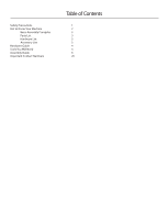
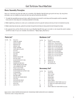
Safety Precautions Get to Know Your Machine Basic Assembly Principles Parts List Hardware List Accessory List Hardware Guide Tools You Will Need Assembly Guide Important Contact Numbers Table of Contents 1 2 3 3 3 3 4 4 5 20 - Bowflex Sport | Assembly Manual - Page 3
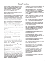
attaching rods. • Never use dumbbells or other weight equipment to incrementally increase the weight resistance. • Never attempt to exercise with more resistance than you are physically able to handle. Use only the Power Rods® that came with your Bowflex Sport® home gym. • Keep cables and Power - Bowflex Sport | Assembly Manual - Page 4
Bowflex Sport® home gym is on a hard, level surface. Assemble your Bowflex Sport® home gym in the location where you intend to use it, as the Bowflex Sport® home gym does not go T through doors easily once fully assembled. Allow a workout area of at least 8'4" x 6'6" (2.6 m x 2.0 m) of free - Bowflex Sport | Assembly Manual - Page 5
BENT LAT BAR HAND GRIPS ROWING BELT SNAP HOOKS SQUAT STRAPS ROD CABLES W/ 2 SNAP HOOKS (attached) LAT CABLES W/ 2 SNAP HOOKS (attached) LEG CABLE SQUAT CABLES W/ 2 SNAP HOOKS (attached) NOTE: LEAVE ALL CABLES WRAPPED AND BAGGED UNTIL YOUR BOWFLEX SPORT® HOME GYM IS FULLY ASSEMBLED. *Specifications - Bowflex Sport | Assembly Manual - Page 6
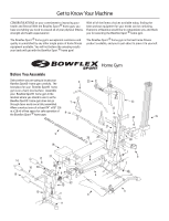
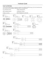
Hardware Guide Tools You Will Need You will need the following tools to complete the assembly of your Bowflex Sport® home gym. If you don't have these tools, you can find them at any hardware or department store for a reasonable price. • 1/2" combination wrench • Rubber mallet (optional) • 9/16 - Bowflex Sport | Assembly Manual - Page 7
1 Mounting Channels Forward Screws H N 1 O 2 Base Platform Tubes Step 2 - Attach the Base Legs to the Base Platform Locate the following items: • From Step 1 - Base Platform/Lower Lat Tower Assembly • Item #3 - Base Right Leg - Do not unwrap cables! • Item #4 - Base Left Leg - Do not unwrap - Bowflex Sport | Assembly Manual - Page 8
Assembly Guide Step 3 - Attach the Squat Platform to the Main Assembly Locate the following items: • From Step 2 - Base Platform/Lat Tower (Main) Assembly • Item #5 - Squat Platform • Item #I - (2) 3/8" X 3 1/4" Button Head Screws • Item #N - (4) 3/8" Washers • Item #O - (2) 3/8" Nylock Nuts • Item - Bowflex Sport | Assembly Manual - Page 9
Assembly Guide Step 4 - Attach the Chest Bar with Pulleys to the Main Assembly Locate the following items: • From Step 3 - Main Assembly • Item #6 - Chest Bar w/ Pulleys - Do not unwrap cables! • Item #K - (2) 3/8" X 5" Button Head Screws • Item #N - (4) 3/8" Washers • Item #O - (2) 3/8" Nylock - Bowflex Sport | Assembly Manual - Page 10
Assembly Guide Step 6 - Attach the Seat Rail to the Seat Assembly Locate the following items: • From Step 5 - Seat Pad/Seat Bracket Assembly • Item #9 - Seat Rail Undo the twist ties from the Rail Pivot Bushings and remove the Bushings. Set aside until the end of this step. Line up the Seat Rail ( - Bowflex Sport | Assembly Manual - Page 11
Assembly Guide Step 8 - Attach the Rear Leg to the Seat Rail Locate the following items: • From Step 6 - Seat Rail Assembly • From Step 7 - Rear Leg Assembly • Item #J - (1) 3/8" X 4 1/4" Button Head Screw • Item #N - (2) 3/8" Washers • Item #O - (1) 3/8" Nylock Nut • Item #Q - (2) Bolt Covers Undo - Bowflex Sport | Assembly Manual - Page 12
Assembly Guide Step 9 - Attach the Seat Rail to the Main Assembly Locate the following items: • From Step 4 - Main Assembly • From Step 8 - Seat Rail Assembly • Item #12 - Seat Rail Knob • Item #J - (1) 3/8" X 4 1/4" Button Head Screw • Item #N - (2) 3/8" Washers • Item #O - (1) 3/8" Nylock Nut • - Bowflex Sport | Assembly Manual - Page 13
Assembly Guide Step 10 - Attach the Leg Extension Pivot Tube Locate the following items: • Item #13 - Leg Extension Pivot Tube • From Step 9 - Main Assembly • Item #30 - Lock Out Pin • Item #G - (1) 3/8" X 2 3/4" Button Head Screw • Item #N - (2) 3/8" Washers • Item #O - (1) 3/8" Nylock Nut • Item - Bowflex Sport | Assembly Manual - Page 14
the hole closest to the Seat. There are two holes lower hole for your height - the Roller should Use a Rubber Mallet to secure the End Caps. Figure 11 15 14 Step 12 - Attach Leg Cable to the Leg Extension Locate the following items: • From Step 11 - Main Assembly • Item #AA - (1) Leg Cable - Bowflex Sport | Assembly Manual - Page 15
Assembly Guide Step 13 - Assemble the Leg Extension Seat Locate the following items: • Item #19 - Leg Extension Seat Pad • Item #21 - Leg Extension Seat Support Tube • Item #C - (4) 5/16" X 3/4" Button Head Screws • Item #M - (4) 5/16" Washers Figure 13 21 Rail Bracket Place the Leg Extension - Bowflex Sport | Assembly Manual - Page 16
Extension Seat Assembly, reverse this procedure. Figure 14 Leg Extension Seat Support Tube Bracket Hooks Roller Tube Spacers Back Edge Step 15 - Attach the Lat Cross Bar to the Upper Lat Tower Locate the following items: • Item #22 - Lat Cross Bar - Do not unwrap cables! • Item #23 - Upper Lat - Bowflex Sport | Assembly Manual - Page 17
installed during Step 16. Figure 16 Upper Lat Tower N E Lower Lat Tower Step 17 - Attach the Rod Box with Power Rods® to the Rod Box Frame Locate the following items: Figure 17 • Item #24 - Rod Box Frame • Item #25 - Rod Box with Power Rods® • Item #B - (3) #10 X 1" Phillips Head Screws • Item - Bowflex Sport | Assembly Manual - Page 18
Assembly Guide Step 18 - Attach the Rod Box Frame to the Lat Tower Locate the following items: • From Step 16 - Main Assembly • From Step 17 - Rod Box/Frame Assembly to push the Power Rods® out of the way to insert the screws into the holes. Attach the Faceplate to the Lower Lat Tower by threading - Bowflex Sport | Assembly Manual - Page 19
5 - Seat Assembly (underneath) Using an Allen Wrench (included) and a combination wrench, tighten the top nut & bolt on the Seat Assembly (see Figure 21). Take care that the Seat Assembly can still freely slide without resistance along the Seat Rail when you are seated. Note: The Seat Assembly will - Bowflex Sport | Assembly Manual - Page 20
and connect the Cables to your new Bowflex Sport® Home Gym. Seat Assembly Step 23 - Route the Rod Cables Locate the following items: • Item #S - (2) Hand Grips • Item #V - (2) Snap Hooks • Item #Y - (2) Rod Cables with (2) Snap Hooks (attached) Figure 23 - Rod Cables Rod Cap Rod Hook Unwrap the - Bowflex Sport | Assembly Manual - Page 21
Snap Hook on the Chest Bar. Fasten the Snap Hook attached to the Squat Cables to the corresponding Squat Bar "D" Ring. Repeat for remaining Squat Cable. CONGRATULATIONS! You have successfully completed assembly of your Bowflex Sport® Home Gym! Please inspect your machine to ensure that all fasteners - Bowflex Sport | Assembly Manual - Page 22
Washington, USA 98683 Phone: 800-NAUTILUS (800-628-8458) For technical assistance and a list of distributors in your area, please call or fax one of the following numbers. • INTERNATIONAL CUSTOMER SERVICE: Nautilus International S.A. Rue Jean Prouvé 6 1762 Givisiez / Switzerland Tel: + 41-26-460-77 - Bowflex Sport | Assembly Manual - Page 23
- Bowflex Sport | Assembly Manual - Page 24
have any questions regarding your Bowflex Sport® Home Gym or any instructions found in this manual, please call 1-800-605-3369 for assistance. ©2004 Nautilus Inc. All rights reserved. 1400 N.E. 136th Ave., Vancouver, WA 98684. Bowflex, Bowflex Sport, Power Rod and the Bowflex and Nautilus logos are
-
 1
1 -
 2
2 -
 3
3 -
 4
4 -
 5
5 -
 6
6 -
 7
7 -
8
-
9
-
10
-
11
-
12
-
13
-
14
-
15
-
16
-
17
-
18
-
19
-
20
-
21
-
22
-
23
-
24
 |
 |

001-6961 Rev B (06-19-06)
The
Bowflex Sport
®
Home Gym
Assembly Instructions
�±²³´
���±²³�´µ¶·±¸³¹