Bowflex Sport Assembly Manual - Page 13
Step 10 - Attach the Leg Extension Pivot Tube
 |
View all Bowflex Sport manuals
Add to My Manuals
Save this manual to your list of manuals |
Page 13 highlights
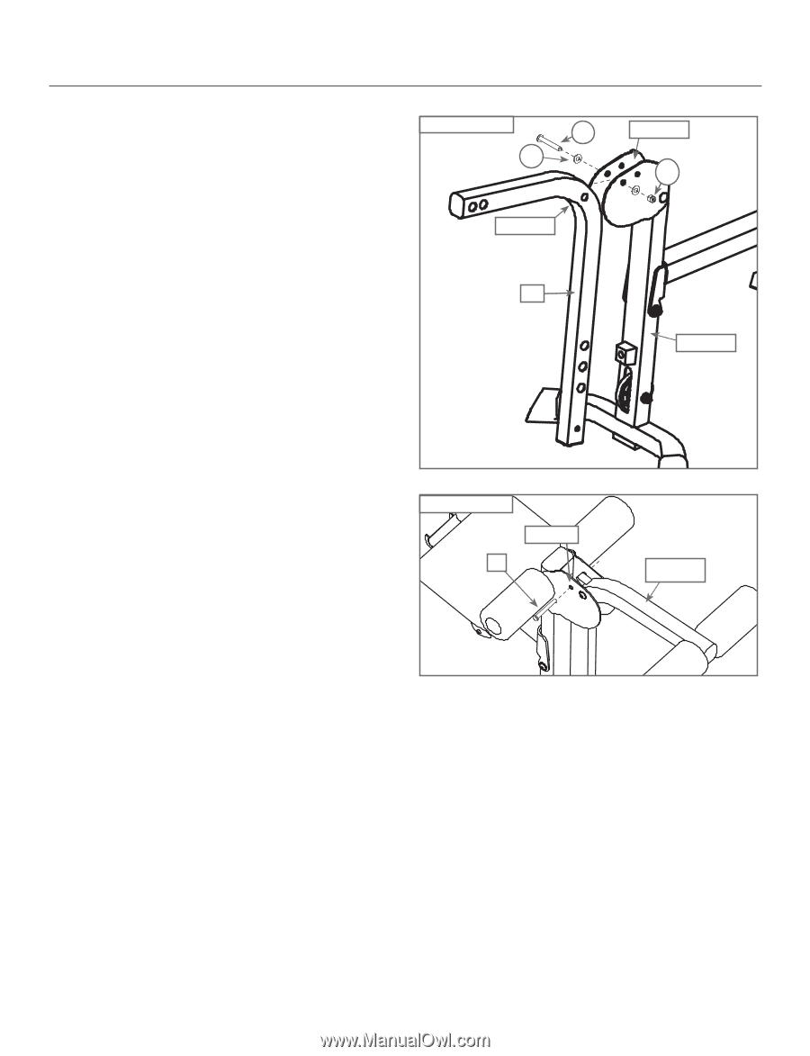
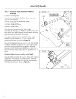
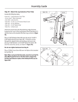
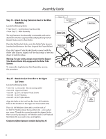
Assembly Guide Step 10 - Attach the Leg Extension Pivot Tube Locate the following items: • Item #13 - Leg Extension Pivot Tube • From Step 9 - Main Assembly • Item #30 - Lock Out Pin • Item #G - (1) 3/8" X 2 3/4" Button Head Screw • Item #N - (2) 3/8" Washers • Item #O - (1) 3/8" Nylock Nut • Item #Q - (1) Bolt Cover Undo the twist ties from the Pivot Bushings. Align the holes located on the"curve"of the Leg Extension PivotTube (Item #13) with the holes on the bracket of the Rear Leg, as shown in Figure 10a. Place (1) 3/8" Washer (Item #N) over the end of (1) 3/8" X 2 3/4" Button Head Screw (Item #G). Thread the screw through the aligned holes and bushings and secure by placing (1) 3/8" Washer and (1) 3/8" Nylock Nut (Item #O) over the end of the screw, as shown in Figure 10a. Do not over-tighten hardware from Step 10. Place (1) Bolt Cover (Item #Q) over the Nylock Nut installed during Step 10. Note: When storing the Rail Assembly, insert the Lock Out Pin (Item #30) through the holes in the Pivot Tube to temporarily hold the Leg Extension in place while folding the Rail up (see Figure 10b). Figure 10a G N "Curve" 13 Figure 10b 30 Holes Bracket O Rear Leg Leg Extension 11
-
 1
1 -
2
-
3
-
4
-
5
-
6
-
7
-
 8
8 -
 9
9 -
 10
10 -
 11
11 -
 12
12 -
 13
13 -
 14
14 -
 15
15 -
 16
16 -
 17
17 -
 18
18 -
19
-
20
-
21
-
22
-
23
-
24
 |
 |