Bowflex Sport Assembly Manual - Page 7
Assembly Guide
 |
View all Bowflex Sport manuals
Add to My Manuals
Save this manual to your list of manuals |
Page 7 highlights
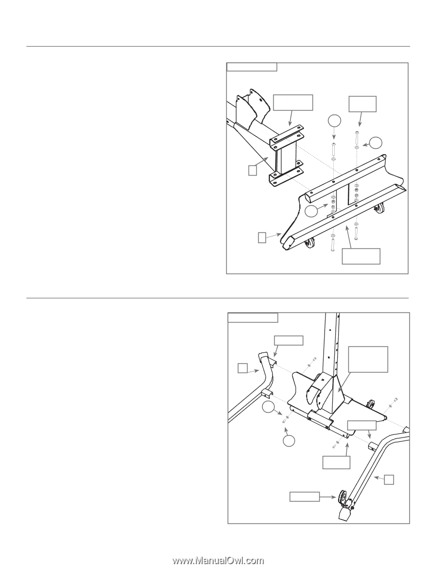
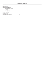
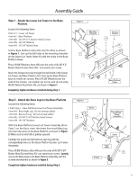
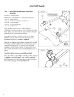
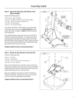
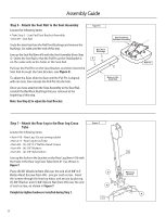
Assembly Guide Step 1 - Attach the Lower Lat Tower to the Base Platform Locate the following items: • Item #1 - Lower Lat Tower • Item #2 - Base Platform • Item #H - (4) 3/8" X 3" Button Head Screws • Item #N - (8) 3/8" Washers • Item #O - (4) 3/8" Nylock Nuts Set the Base Platform (Item #2) onto the floor as shown in Figure 1. Line up the bolt holes in the mounting channels on the Lower Lat Tower (Item #1) with the holes in the Base Platform tubes. Place (4) 3/8" Washers (Item #N) over the ends of (4) 3/8" X 3" Button Head Screws (Item #H) - one washer per screw. Insert the forward screws through the bolt holes in the Lower Lat Tower and Base Platform first, then tip the Base Platform back to install rear screws. Place (4) 3/8" Washers over the ends of the screws, one washer per screw, and secure using (4) 3/8" Nylock Nuts (Item #O), as shown in Figure 1. Completely tighten hardware installed during Step 1. Figure 1 Mounting Channels Forward Screws H N 1 O 2 Base Platform Tubes Step 2 - Attach the Base Legs to the Base Platform Locate the following items: • From Step 1 - Base Platform/Lower Lat Tower Assembly • Item #3 - Base Right Leg - Do not unwrap cables! • Item #4 - Base Left Leg - Do not unwrap cables! • Item #E - (4) 3/8" X 3/4" Button Head Screws • Item #N - (4) 3/8" Washers With the Base Platform/Lower Lat Tower Assembly (from Step 1) on the floor, insert the stems from each Base Leg into the tube ends on the Base Platform, as shown in Figure 2. Make sure to orient the 2 pulleys upward. Carefully line up the two bolt holes on each Leg with the corresponding holes on the Base Platform/Lower Lat Tower Assembly. Place (4) 3/8" Washers (Item #N) over the ends of (4) 3/8" X 3/4" Button Head Screws (Item #E) - one washer per screw. Loosely secure the Base Legs to the Base Platform Assembly with the screws and washers as shown in Figure 2. Completely tighten hardware installed during Step 2. Figure 2 Stems 4 Base Platform/ Lower Lat Tower Assembly N Stems E Tube Ends 3 Pulleys 5
-
 1
1 -
 2
2 -
 3
3 -
 4
4 -
 5
5 -
 6
6 -
 7
7 -
 8
8 -
 9
9 -
 10
10 -
 11
11 -
 12
12 -
13
-
14
-
15
-
16
-
17
-
18
-
19
-
20
-
21
-
22
-
23
-
24
 |
 |