Bowflex Sport Assembly Manual - Page 19
Step 20 - Attach the Faceplate Back Panels, Step 21 - Tighten Lower Bolt on the Seat Bracket - used
 |
View all Bowflex Sport manuals
Add to My Manuals
Save this manual to your list of manuals |
Page 19 highlights
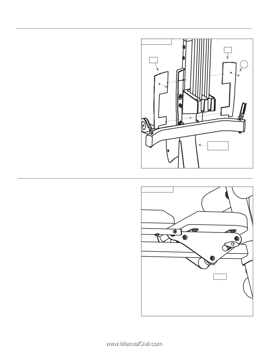
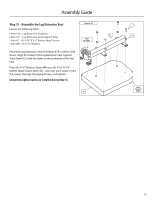
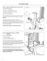
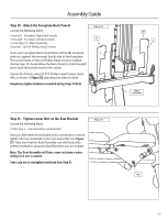
Assembly Guide Step 20 - Attach the Faceplate Back Panels Locate the following items: • Item #27 - Faceplate Right Back Panels • Item #28 - Faceplate Left Back Panels • From Step 19 - Main Assembly • Item #A - (2) #10 Phillips Head Screws Slide each Faceplate Back Panel (Items #27 & 28), textured side out, against the textured (back) side of the Faceplate. The screw heads of the (2) Phillips Head Screws installed during Step 19 should allow the Back Panels to slide beneath them until the panels meet in the center.. Secure the Panels using (2) #10 Phillips Head Screws (Item #A), as shown in Figure 20, attaching one side at a time. Completely tighten hardware installed during Steps 19 & 20. Figure 20 27 Step 21 - Tighten Lower Bolt on the Seat Bracket Locate the following items: • From Step 5 - Seat Assembly (underneath) Using an Allen Wrench (included) and a combination wrench, tighten the top nut & bolt on the Seat Assembly (see Figure 21). Take care that the Seat Assembly can still freely slide without resistance along the Seat Rail when you are seated. Note: The Seat Assembly will have some resistance when rolling if no one is seated. Take care not to overtighten hardware from Step 21. Figure 21 28 A Main Assembly Nut 17
-
 1
1 -
2
-
3
-
4
-
5
-
6
-
7
-
8
-
9
-
10
-
11
-
12
-
13
-
 14
14 -
 15
15 -
 16
16 -
 17
17 -
 18
18 -
 19
19 -
 20
20 -
 21
21 -
 22
22 -
 23
23 -
 24
24
 |
 |