Bowflex Sport Assembly Manual - Page 14
Step 11 - Attach the Rollers to the Leg Extension, Step 12 - Attach Leg Cable to the Leg Extension - height
 |
View all Bowflex Sport manuals
Add to My Manuals
Save this manual to your list of manuals |
Page 14 highlights
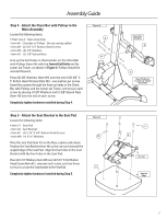
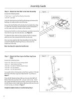
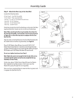
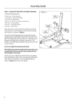
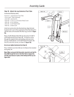
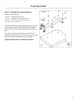
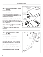
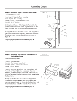
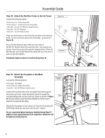
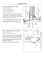
Assembly Guide Step 11 - Attach the Rollers to the Leg Extension Locate the following items: • From Step 10 - Main Assembly • Item #14 - Foam Rollers • Item #15 - Foam Roller End Caps • Item #16 - Short Chrome Roller Tubes • Item #17 - Long Chrome Roller Tube • Item #18 - Roller Tube Spacers There are (3) Chrome Roller Tubes on the Leg Extension. Place the Long Chrome Roller Tube (Item #17) through the hole closest to the Seat. There are two holes possible in the Leg Extension Pivot Tube for the lower of the Short Chrome Roller Tubes (Item #16). Select the correct lower hole for your height - the Roller should rest on your lower shin above the ankle. Insert the (3) Chrome Roller Tubes through the holes on the Leg Extension Pivot Tube and Rear Leg, as shown in Figure 11. Slide (2) Roller Tube Spacers (Item #18) over each end of the Long Chrome Roller Tube. Then, slide (2) Foam Rollers (Item #14) over the ends of all three tubes. Cap the Roller Tubes with the (6) Foam Roller End Caps (Item #15). Note: Use a Rubber Mallet to secure the End Caps. Figure 11 15 14 Step 12 - Attach Leg Cable to the Leg Extension Locate the following items: • From Step 11 - Main Assembly • Item #AA - (1) Leg Cable • Item #F - (1) 3/8" X 2 1/2" Button Head Screw • Item #N - (2) 3/8" Washers • Item #O - (1) 3/8" Nylock Nut • Item #Q - (1) Bolt Cover Slide the hooked end of the Leg Cable beneath the Leg Extension Pulley and into the hole on the Leg Extension Pivot Tube, as shown in Figure 12. Place (1) 3/8" Washer (Item #N) over the end of (1) 3/8" X 2 1/2" Button Head Screw (Item #F). Thread the screw through holes in the Leg Extension and cable end. Place (1) 3/8" Washer and (1) 3/8" Nylock Nut (Item #O) over the end of the screw, as shown in Figure 12, and tighten. Completely tighten hardware installed during Step 12. Place (1) Bolt Cover (Item #Q) over the Nylock Nut installed during Step 12. Figure 12 N O 18 17 16 F AA
-
 1
1 -
2
-
3
-
4
-
5
-
6
-
7
-
8
-
 9
9 -
 10
10 -
 11
11 -
 12
12 -
 13
13 -
 14
14 -
 15
15 -
 16
16 -
 17
17 -
 18
18 -
 19
19 -
20
-
21
-
22
-
23
-
24
 |
 |
