Brother International RH-981A Instruction Manual - Spanish - Page 19
Installing the spool stand, 3-10. Installing the hand switch
 |
View all Brother International RH-981A manuals
Add to My Manuals
Save this manual to your list of manuals |
Page 19 highlights
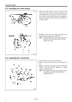
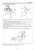
3-9. Installing the spool stand 3. INSTALLATION 1. To assemble the spool stand (1), follow the instructions in the manual that came with the spool stand (1). 2. Secure the spool stand (1) to the rear right corner of the work table with the washer and nut (2). 2989Q 3-10. Installing the hand switch Install the hand switch (1) with the two screws (2). 3129Q 3-11. Installing the air unit and the valve unit Valve unit 2387Q Air unit 2992Q Installation position 1. Install the air unit (1) to the underside of the work table with the two screws (2). 2. Install the valve unit (3) with the two screws (4). 3. Connect air tube No. 15 to the intermediate joint (5) of the air unit (1) and to the joint (6) of the valve unit (3), and connect air tube No. 16 to joints (7) and (8). Connecting the valve cables Insert the cable (9) which is coming out of the valve unit to the 2-pin connector (10) of the valve cable assembly. RH-981A 12
-
 1
1 -
2
-
3
-
4
-
5
-
6
-
7
-
8
-
9
-
10
-
11
-
12
-
13
-
 14
14 -
 15
15 -
 16
16 -
 17
17 -
 18
18 -
 19
19 -
 20
20 -
 21
21 -
 22
22 -
 23
23 -
 24
24 -
25
-
26
-
27
-
28
-
29
-
30
-
31
-
32
-
33
-
34
-
35
-
36
-
37
-
38
-
39
-
40
-
41
-
42
-
43
-
44
-
45
-
46
-
47
-
48
-
49
-
50
-
51
-
52
-
53
-
54
-
55
-
56
-
57
-
58
-
59
-
60
-
61
-
62
-
63
-
64
-
65
-
66
-
67
-
68
-
69
-
70
-
71
-
72
-
73
-
74
-
75
-
76
-
77
-
78
-
79
-
80
-
81
-
82
-
83
-
84
-
85
-
86
-
87
-
88
-
89
 |
 |
