Brother International RH-981A Instruction Manual - Spanish - Page 6

Contents, Names Of Each Part, Specifications, Installation, Lubrication, Correct Use, Operation

Page 6 highlights

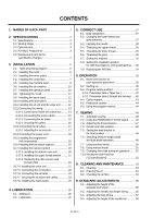
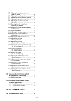
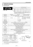
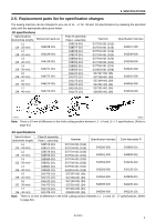
CONTENTS 1. NAMES OF EACH PART 1 2. SPECIFICATIONS 2 2-1. Specifications 2 2-2. Sewing shape 3 2-3. Optional parts 3 2-4. PD-9810, Programmer 3 2-5. Replacement parts list for specification changes 4 3. INSTALLATION 5 3-1. Table processing diagram 5 3-2. Installing the motor 6 3-3. Installing the motor pulley 7 3-4. Installing the control box 7 3-5. Installing the machine head 8 3-6. Installing the oil container 10 3-7. Installing the operation panel 10 3-8. Tightening the V-belt 11 3-9. Installing the spool stand 12 3-10.Installing the hand switch 12 3-11.Installing the air unit and the valve unit .......... 12 3-12. Connecting the wiring 13 3-12-1. Connections inside the control box ......... 14 3-12-2. Connecting the motor cables 15 3-12-3. Connecting the air tubes 15 3-12-4. Securing the cables 16 3-13.Connecting the air tubes 17 3-13-1. Adjusting the air pressure 17 3-14.Connecting the power cord 18 3-15.Installing the programmer (sold separately 19 3-16.Installing the foot switch (option 19 3-17.Installing the indexer (option 20 3-17-1. Installing the indexer main unit 20 3-17-2. Installing the upper thread presser ......... 21 3-17-3. Replacing the plate presser and presser plate 21 3-17-4. Installing the valve unit 21 3-17-5. Connecting the connectors 22 3-17-6. Connecting the air tubes 23 3-17-7. Securing the air tubes and cables 23 3-17-8. Installing the hand switch 24 4. LUBRICATION 25 4-1. Adding oil 25 4-2. Lubrication 25 5. CORRECT USE 27 5-1. Data initialization 27 5-2. Changing the lower thread and gimp trimming 27 5-3. Installing the needle 28 5-4. Threading the upper thread 28 5-5. Threading the lower thread 29 5-6. Threading the gimp 30 5-7. Setting the material 31 5-8. Setting the installation position for cloth feed plate (L) (-52 specifications) ...... 33 5-9. Replacing the PROMs 34 6. OPERATION 35 6-1. Name and function of each operation panel item 35 6-2. Starting up 36 6-3. Program setting method 37 6-3-1. Parameter table ( Taper bar 37 6-3-2. Parameter table ( Straight bar tacking ) ......40 6-4. Cycle program 43 6-5. Production counter 44 6-6. Using the program memos 44 7. SEWING 45 7-1. Automatic sewing 45 7-2. Using the EMERGENCY STOP switch ......... 46 7-3. Adjusting the thread tension 47 7-4. Needle and knife position 48 7-5. Setting the feed bracket to the front position 49 7-6. Switching between single-pedal and dual-pedal operation 49 7-7. Using test feed mode 50 7-8. Using manual mode 51 7-9. Changing the mode during an operation ........ 52 7-10.Moving the cloth feed bar (-52 specifications 52 8. CLEANING AND MAINTENANCE 53 8-1. Cleaning 53 8-2. Draining the oil 54 8-3. Checking the air filter 54 9. STANDARD ADJUSTMENTS 55 9-1. Adjusting the height of the spreader and looper 55 9-2. Adjusting the needle and looper timing........... 56 9-3. Adjusting the loop stroke 57 9-4. Adjusting the height of the needle bar 58 RH-981A

  • 1
  • 2
  • 3
  • 4
  • 5
  • 6
  • 7
  • 8
  • 9
  • 10
  • 11
  • 12
  • 13
  • 14
  • 15
  • 16
  • 17
  • 18
  • 19
  • 20
  • 21
  • 22
  • 23
  • 24
  • 25
  • 26
  • 27
  • 28
  • 29
  • 30
  • 31
  • 32
  • 33
  • 34
  • 35
  • 36
  • 37
  • 38
  • 39
  • 40
  • 41
  • 42
  • 43
  • 44
  • 45
  • 46
  • 47
  • 48
  • 49
  • 50
  • 51
  • 52
  • 53
  • 54
  • 55
  • 56
  • 57
  • 58
  • 59
  • 60
  • 61
  • 62
  • 63
  • 64
  • 65
  • 66
  • 67
  • 68
  • 69
  • 70
  • 71
  • 72
  • 73
  • 74
  • 75
  • 76
  • 77
  • 78
  • 79
  • 80
  • 81
  • 82
  • 83
  • 84
  • 85
  • 86
  • 87
  • 88
  • 89

RH-981A
CONTENTS
1.
NAMES OF EACH PART
................................
1
2. SPECIFICATIONS
..............................................
2
2-1. Specifications
......................................................
2
2-2. Sewing shape
.....................................................
3
2-3. Optional parts
......................................................
3
2-4. PD-9810, Programmer
.......................................
3
2-5. Replacement parts list for
specification changes
.........................................
4
3. INSTALLATION
....................................................
5
3-1.
Table processing diagram
................................
5
3-2.
Installing the motor
............................................
6
3-3.
Installing the motor pulley
.................................
7
3-4.
Installing the control box
...................................
7
3-5.
Installing the machine head
..............................
8
3-6.
Installing the oil container
...............................
10
3-7.
Installing the operation panel
..........................
10
3-8.
Tightening the V-belt
.......................................
11
3-9.
Installing the spool stand
................................
12
3-10. Installing the hand switch
................................
12
3-11. Installing the air unit and the valve unit
..........
12
3-12. Connecting the wiring
......................................
13
3-12-1. Connections inside the control box
.........
14
3-12-2. Connecting the motor cables
...................
15
3-12-3. Connecting the air tubes
..........................
15
3-12-4. Securing the cables
..................................
16
3-13. Connecting the air tubes
..................................
17
3-13-1. Adjusting the air pressure
........................
17
3-14. Connecting the power cord
.............................
18
3-15. Installing the programmer
(sold separately)
...............................................
19
3-16. Installing the foot switch (option)
.....................
19
3-17. Installing the indexer (option)
..........................
20
3-17-1. Installing the indexer main unit
................
20
3-17-2. Installing the upper thread presser
.........
21
3-17-3. Replacing the plate presser and
presser plate
............................................
21
3-17-4. Installing the valve unit
................................
21
3-17-5. Connecting the connectors
..........................
22
3-17-6. Connecting the air tubes
.............................
23
3-17-7. Securing the air tubes and cables
...............
23
3-17-8. Installing the hand switch
.............................
24
4. LUBRICATION
......................................................
25
4-1.
Adding oil
.........................................................
25
4-2. Lubrication
.......................................................
25
5.
CORRECT USE
.................................................
27
5-1.
Data initialization
...............................................
27
5-2. Changing the lower thread and
gimp trimming
..................................................
27
5-3.
Installing the needle
.........................................
28
5-4.
Threading the upper thread
.............................
28
5-5.
Threading the lower thread
..............................
29
5-6.
Threading the gimp
.........................................
30
5-7.
Setting the material
..........................................
31
5-8.
Setting the installation position
for cloth feed plate (L) (-52 specifications)
......
33
5-9.
Replacing the PROMs
.....................................
34
6. OPERATION
.........................................................
35
6-1. Name and function of
each operation panel item
................................
35
6-2. Starting up
.........................................................
36
6-3. Program setting method
..................................
37
6-3-1. Parameter table ( Taper bar )
.....................
37
6-3-2. Parameter table ( Straight bar tacking )
......
40
6-4. Cycle program
..................................................
43
6-5. Production counter
...........................................
44
6-6. Using the program memos
..............................
44
7. SEWING
................................................................
45
7-1.
Automatic sewing
.............................................
45
7-2.
Using the EMERGENCY STOP switch
.........
46
7-3.
Adjusting the thread tension
............................
47
7-4.
Needle and knife position
.................................
48
7-5.
Setting the feed bracket to
the front position
...............................................
49
7-6.
Switching between single-pedal
and dual-pedal operation
.................................
49
7-7.
Using test feed mode
.......................................
50
7-8.
Using manual mode
.........................................
51
7-9.
Changing the mode during an operation
........
52
7-10. Moving the cloth feed bar
(-52 specifications)
...........................................
52
8.
CLEANING AND MAINTENANCE
............
53
8-1. Cleaning
...........................................................
53
8-2.
Draining the oil
.................................................
54
8-3.
Checking the air filter
........................................
54
9. STANDARD ADJUSTMENTS
.......................
55
9-1.
Adjusting the height of the
spreader and looper
.........................................
55
9-2.
Adjusting the needle and looper timing
...........
56
9-3.
Adjusting the loop stroke
..................................
57
9-4.
Adjusting the height of the needle bar
.............
58