Brother International XR9550 Operation Manual - Page 8
Names Of Machine Parts, And Their Functions
 |
View all Brother International XR9550 manuals
Add to My Manuals
Save this manual to your list of manuals |
Page 8 highlights
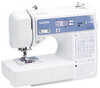
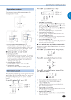
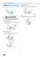
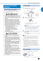
KNOWING YOUR SEWING MACHINE NAMES OF MACHINE PARTS AND THEIR FUNCTIONS The illustrations in this operation manual may differ from the actual machine. The main parts D Foot controller (page 9) E Foot controller jack/socket (page 9) F Feed dog position lever (page 37 and 42) G Presser foot lever (page 16) H Thread guide (page 12 and 17) I Thread guide cover (page 17) J Handle Carry the sewing machine by its handle when transporting the machine. Needle and presser foot section 1 Bobbin winder (page 11) 2 Upper tension-control dial (page 28) 3 Bobbin-winding thread guide and pre-tension disc (page 12) 4 Thread take-up lever (page 17) 5 Thread cutter (page 27) 6 Flat bed attachment with accessory compartment (page 5 and 30) 7 Operation buttons (page 7) 8 Operation panel (page 7) 9 Spool pin (page 8, 11 and 16) < Handwheel This is used to manually raise and lower the needle. A Air vent This vent allows the air surrounding the motor to circulate. Do not cover the air vent while the sewing machine is being used. B Main power and sewing light switch (page 9) C Jack/socket connector (page 9) 6 1 Needle threader (for models equipped with the needle threader) (page 18) 2 Buttonhole lever (page 35 and 43) 3 Presser foot holder The presser foot is installed onto the presser foot holder. 4 Presser foot holder screw Use the presser foot holder screw to hold the presser foot holder in place. 5 Presser foot The presser foot applies pressure consistently on the fabric as the sewing takes place. Attach the appropriate presser foot for the selected stitching. 6 Needle plate cover release Use when removing the needle plate cover. 7 Needle plate cover 8 Feed dogs The feed dogs feed the fabric in the sewing direction. 9 Quick-set bobbin (for models equipped with the quickset bobbin) You can start sewing without pulling up the bobbin thread. 0 Bobbin cover A Needle plate The needle plate is marked with guides for sewing straight seams. B Needle bar thread guide (page 18) C Presser foot lever Raises and lowers the presser foot. D Needle clamp screw
-
 1
1 -
2
-
 3
3 -
 4
4 -
 5
5 -
 6
6 -
 7
7 -
 8
8 -
 9
9 -
 10
10 -
 11
11 -
 12
12 -
 13
13 -
14
-
15
-
16
-
17
-
18
-
19
-
20
-
21
-
22
-
23
-
24
-
25
-
26
-
27
-
28
-
29
-
30
-
31
-
32
-
33
-
34
-
35
-
36
-
37
-
38
-
39
-
40
-
41
-
42
-
43
-
44
-
45
-
46
-
47
-
48
-
49
-
50
-
51
-
52
-
53
-
54
-
55
-
56
-
57
-
58
-
59
-
60
-
61
-
62
-
63
-
64
-
65
-
66
-
67
-
68
-
69
-
70
-
71
-
72
-
73
-
74
-
75
-
76
 |
 |
