Campbell Scientific 253 253-L and 257-L (Watermark 200) Soil Matric Potential - Page 23
Calculate Soil Water Potential
 |
View all Campbell Scientific 253 manuals
Add to My Manuals
Save this manual to your list of manuals |
Page 23 highlights
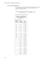
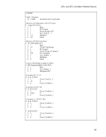
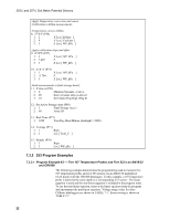
253-L and 257-L Soil Matric Potential Sensors Rs = R1 ⎜⎜⎝⎛ (1 X −X ) ⎟⎟⎠⎞ Where X = Vs/Vx (output from Instruction 5). A multiplier of 1, which represents the value of the reference resistor in kΩ, should be used to output sensor resistance (Rs) in terms of kΩ. 7.2.3 Calculate Soil Water Potential The datalogger can calculate soil water potential (kPa) from the sensor resistance (Rs) and soil temperature (Ts). See TABLE 7-3. The need for a precise soil temperature measurement should not be ignored. Soil temperatures vary widely where placement is shallow and solar radiation impinges on the soil surface. A soil temperature measurement may be needed in such situations, particularly in research applications. Many applications, however, require deep placement (12 to 25 cm) in soils shaded by a crop canopy. A common practice for deep or shaded sensors is to assume the air temperature at sunrise will be close to what the soil temperature will be for the day. 7.2.3.1 Linear Relationship For applications where soil water potential is in the range of 0 to -200 kPa, water potential and temperature responses of the 257 can be assumed to be linear (measurements beyond -125 kPa have not been verified, but work in practice). The following equation normalizes the resistance measurement to 21°C. R21 = 1− Rs (0.018 * dT ) where R21 = resistance at 21°C Rs = the measured resistance dT = Ts - 21 Ts = soil temperature Water potential is then calculated from R21 with the relationship, SWP = 7.407 * R21 − 3.704 where SWP is soil water potential in kPa 17
-
 1
1 -
2
-
3
-
4
-
5
-
6
-
7
-
8
-
9
-
10
-
11
-
12
-
13
-
14
-
15
-
16
-
17
-
 18
18 -
 19
19 -
 20
20 -
 21
21 -
 22
22 -
 23
23 -
 24
24 -
 25
25 -
 26
26 -
 27
27 -
 28
28 -
29
-
30
-
31
-
32
-
33
-
34
-
35
-
36
 |
 |
