Campbell Scientific 253 253-L and 257-L (Watermark 200) Soil Matric Potential - Page 25
Example Programs
 |
View all Campbell Scientific 253 manuals
Add to My Manuals
Save this manual to your list of manuals |
Page 25 highlights
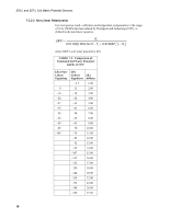
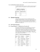
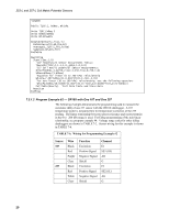
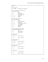
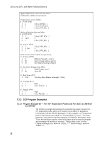
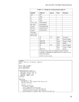
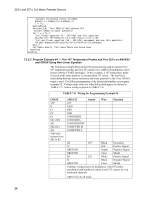
253-L and 257-L Soil Matric Potential Sensors 7.2.3.3 Soil Water Matric Potential in Other Units To report measurement results in other units, multiply the result from the linear or non-linear equation by the appropriate conversion constant from TABLE 7-4. TABLE 7-4. Conversion of Matric Potential to Other Units Desired Unit kPa MPa Bar Multiply Result By 1.0 0.001 0.01 7.3 Example Programs These examples show programs written for the CR1000 and the CR10X dataloggers. With minor changes to excitation and voltage ranges, the code in the CR1000 examples will work with all compatible CRBasic dataloggers (see TABLE 7-1). The code in the CR10X examples will work with all Edlog dataloggers as long as the correct excitation and voltage range is chosen for the P5 instruction (see TABLE 7-2). 7.3.1 257 Program Examples 7.3.1.1 Program Example #1 - CR1000 with One 107 and One 257 The following example demonstrates the programming used to measure the resistance (kΩ) of one 257 sensor with the CR1000 datalogger. A 107 temperature probe is measured first for temperature correction of the 257 reading. The linear equation is used and the non-linear equation is included in the program notes. To use the non-linear equation, remove the linear equation from the program and uncomment the non-linear equation. Voltage range codes for other CRBasic dataloggers are shown in TABLE 7-1. Sensor wiring for this example is shown in TABLE 7-5. TABLE 7-5. Wiring for Programming Example #1 Sensor 107 257 Wire Black Red Purple Clear Black Red White Clear Function Excitation Positive Signal Negative Signal Shield Excitation Positive Signal Negative Signal Shield Channel EX1 SE1 (1H) Ground Ground EX2 SE2 (1L) Ground Ground 19
-
 1
1 -
2
-
3
-
4
-
5
-
6
-
7
-
8
-
9
-
10
-
11
-
12
-
13
-
14
-
15
-
16
-
17
-
18
-
19
-
 20
20 -
 21
21 -
 22
22 -
 23
23 -
 24
24 -
 25
25 -
 26
26 -
 27
27 -
 28
28 -
 29
29 -
 30
30 -
31
-
32
-
33
-
34
-
35
-
36
 |
 |
