Campbell Scientific 253 253-L and 257-L (Watermark 200) Soil Matric Potential - Page 28
Program Examples
 |
View all Campbell Scientific 253 manuals
Add to My Manuals
Save this manual to your list of manuals |
Page 28 highlights
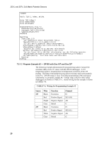
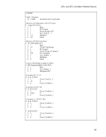
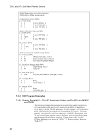
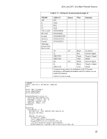
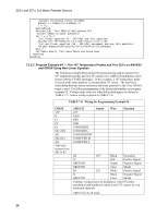
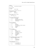
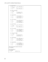
253-L and 257-L Soil Matric Potential Sensors ;Apply Temperature correction and sensor ;Calibration to kOhm measurements. ;Temperature correct kOhms 8: Z=X/Y (P38) 1: 2 X Loc [ kOhms ] 2: 4 Y Loc [ CorFactr ] 3: 3 Z Loc [ WP_kPa ] ;Apply calibration slope and offset 9: Z=X*F (P37) 1: 3 X Loc [ WP_kPa ] 2: 7.407 F 3: 3 Z Loc [ WP_kPa ] 10: Z=X+F (P34) 1: 3 X Loc [ WP_kPa ] 2: -3.704 F 3: 3 Z Loc [ WP_kPa ] ;Send measurements to final storage hourly 11: If time is (P92) 1: 0 Minutes (Seconds --) into a 2: 60 Interval (same units as above) 3: 10 Set Output Flag High (Flag 0) 12: Set Active Storage Area (P80) 1: 1 Final Storage Area 1 2: 60 Array ID 13: Real Time (P77) 1: 1220 Year,Day,Hour/Minute (midnight = 2400) 14: Average (P71) 1: 1 Reps 2: 1 Loc [ Tsoil_C ] 15: Sample (P70) 1: 1 Reps 2: 3 Loc [ WP_kPa ] 7.3.2 253 Program Examples 7.3.2.1 Program Example #3 - Five 107 Temperature Probes and Five 253's on AM16/32 and CR1000 The following example demonstrates the programming used to measure five 107 temperature probes and five 253 sensors on an AM16/32 multiplexer (4x16 mode) with the CR1000 datalogger. In this example, a 107 temperature probe is buried at the same depth as a corresponding 253 sensor. The linear equation is used and the non-linear equation is included in the program notes. To use the non-linear equation, remove the linear equation from the program and uncomment the non-linear equation. Voltage range codes for other CRBasic dataloggers are shown in TABLE 7-1. Sensor wiring is shown in TABLE 7-7. 22
-
 1
1 -
2
-
3
-
4
-
5
-
6
-
7
-
8
-
9
-
10
-
11
-
12
-
13
-
14
-
15
-
16
-
17
-
18
-
19
-
20
-
21
-
22
-
 23
23 -
 24
24 -
 25
25 -
 26
26 -
 27
27 -
 28
28 -
 29
29 -
 30
30 -
 31
31 -
 32
32 -
 33
33 -
34
-
35
-
36
 |
 |