Campbell Scientific 4WFBS1K 4WFBS120, 4WFBS350, 4WFBS1K 4 Wire Full Bridge Ter
Campbell Scientific 4WFBS1K Manual
 |
View all Campbell Scientific 4WFBS1K manuals
Add to My Manuals
Save this manual to your list of manuals |
Campbell Scientific 4WFBS1K manual content summary:
- Campbell Scientific 4WFBS1K | 4WFBS120, 4WFBS350, 4WFBS1K 4 Wire Full Bridge Ter - Page 1
4WFBS120, 4WFBS350, 4WFBS1K 4 Wire Full Bridge Terminal Input Modules Revision: 3/12 Copyright © 1996-2010 Campbell Scientific, Inc. - Campbell Scientific 4WFBS1K | 4WFBS120, 4WFBS350, 4WFBS1K 4 Wire Full Bridge Ter - Page 2
- Campbell Scientific 4WFBS1K | 4WFBS120, 4WFBS350, 4WFBS1K 4 Wire Full Bridge Ter - Page 3
") to be free from defects in materials and workmanship under normal use and service for twelve (12) months from date of shipment unless otherwise specified in the corresponding Campbell pricelist or product manual. Products not manufactured, but that are re-sold by Campbell, are warranted only - Campbell Scientific 4WFBS1K | 4WFBS120, 4WFBS350, 4WFBS1K 4 Wire Full Bridge Ter - Page 4
435) 227-9000. After an applications engineer determines the nature of the problem, an RMA number will be issued. Please write this number clearly on 's expense. Campbell Scientific reserves the right to refuse service on products that were exposed to contaminants that may cause health or safety - Campbell Scientific 4WFBS1K | 4WFBS120, 4WFBS350, 4WFBS1K 4 Wire Full Bridge Ter - Page 5
4WFBS120, 4WFBS350, 4WFBS1K Table of Contents PDF viewers: These page numbers refer to the printed version of this document. Use the PDF reader bookmarks tab for links to specific sections. 1. Function 1 2. Specifications 1 3. Measurement Concepts 2 4. Quarter Bridge Strain 4 4.1 Quarter Bridge - Campbell Scientific 4WFBS1K | 4WFBS120, 4WFBS350, 4WFBS1K 4 Wire Full Bridge Ter - Page 6
4WFBS120, 4WFBS350, 4WFBS1K Table of Contents Figures 1-1. Terminal Input Module with CR1000 1 2-1. Schematic 2 3-1. Strain definition 2 4.1-1. Three wire quarter bridge strain circuit 4 4.1-2. 3-wire ¼ bridge strain wiring 5 4.1-3. 3-wire ¼ bridge strain with multiplexer wiring 5 4.2-1. Two - Campbell Scientific 4WFBS1K | 4WFBS120, 4WFBS350, 4WFBS1K 4 Wire Full Bridge Ter - Page 7
4WFBS120, 4WFBS350, 4WFBS1K 4 Wire Full Bridge Terminal Input Modules (TIM) 1. Function The 4WFBS120, 4WFBS350, and 4WFBS1K Terminal Input Modules (TIM) complete a full Wheatstone bridge for a single strain gage or other sensor that acts as a single variable resistor. The difference between the - Campbell Scientific 4WFBS1K | 4WFBS120, 4WFBS350, 4WFBS1K 4 Wire Full Bridge Ter - Page 8
4WFBS120, 4WFBS350, 4WFBS1K 4 Wire Full Bridge Terminal Input Modules (TIM) FIGURE 2-1. Schematic 3. Measurement Concepts Measuring strain is measuring a change in length. Specifically, the unit strain ( ) (ε ) is the change in length divided by the unstrained length ε = Δ L / L , and thus is - Campbell Scientific 4WFBS1K | 4WFBS120, 4WFBS350, 4WFBS1K 4 Wire Full Bridge Ter - Page 9
zero reading value can be left at 0 (zero measurement is neither recorded nor used). It should be noted the actual result of the full bridge instruction (BrFull) is the millivolts output per volt of excitation (1000 ⋅Vout / Vex ). The StrainCalc 3 - Campbell Scientific 4WFBS1K | 4WFBS120, 4WFBS350, 4WFBS1K 4 Wire Full Bridge Ter - Page 10
the arm holding the active gage instead of a resistor, RD in Figure 4.1.-1 (See Figures 4.3-1, 4.3-2, and 4.3-3). The 4WFBS TIM modules can support all types of these ¼ Bridge Strain circuits. 4.1 Quarter Bridge Strain with 3 Wire Strain Element A 3-wire quarter bridge strain circuit is shown - Campbell Scientific 4WFBS1K | 4WFBS120, 4WFBS350, 4WFBS1K 4 Wire Full Bridge Ter - Page 11
4WFBS120, 4WFBS350, 4WFBS1K 4 Wire Full Bridge Terminal Input Modules (TIM) 4.1.1 Quarter Bridge Strain with 3 Wire Element Wiring Figure 4.1-2 illustrates the wiring of the strain gage to the 4WFBS module and the wiring of the module to the datalogger. It is important that the gage be wired as - Campbell Scientific 4WFBS1K | 4WFBS120, 4WFBS350, 4WFBS1K 4 Wire Full Bridge Ter - Page 12
. This result is the measured bridge output voltage divided by the bridge excitation voltage Vout / Vex . (The actual result of the full bridge instruction is the millivolts output per volt of excitation, 1000 ⋅Vout / Vex ) The result of the zero measurement, 1000 ⋅Vout 0 / Vex can be stored - Campbell Scientific 4WFBS1K | 4WFBS120, 4WFBS350, 4WFBS1K 4 Wire Full Bridge Ter - Page 13
the scan and data storage intervals altered for actual applications. Refer to the datalogger's manuals and/or the CRBasic Editor's help files for detailed information on the program instructions used as well as additional program examples. 4.1.3.1 CRBasic Programming Dataloggers that use CRBasic - Campbell Scientific 4WFBS1K | 4WFBS120, 4WFBS350, 4WFBS1K 4 Wire Full Bridge Ter - Page 14
, a zero reading is often used to offset or remove this apparent strain. Again, see the manual and CRBasic editor's Help file for more in-depth discussion on the instructions. The FieldCalStrain instruction takes care of the underlying math for the zeroing using equation 4.1.2. The LoadFieldCal - Campbell Scientific 4WFBS1K | 4WFBS120, 4WFBS350, 4WFBS1K 4 Wire Full Bridge Ter - Page 15
program. There are slight differences such as range codes and the fact that the CR1000 does not have a Slot parameter for its measurement instructions. This program is more similar to what a CR800, CR3000, or a CR5000 program would look like than the CR9000X program. ' Program name: STRAIN0.CR1 - Campbell Scientific 4WFBS1K | 4WFBS120, 4WFBS350, 4WFBS1K 4 Wire Full Bridge Ter - Page 16
4WFBS120, 4WFBS350, 4WFBS1K 4 Wire Full Bridge Terminal Input Modules (TIM) Example Program 4.3. CR1000 ¼ Bridge Strain using an AM16/32B Multiplexer with 16 reps and zero offset This example program has 16 strain gages multiplexed through an AM16/32 Multiplexer and uses FieldCalStrain for zeroing. - Campbell Scientific 4WFBS1K | 4WFBS120, 4WFBS350, 4WFBS1K 4 Wire Full Bridge Ter - Page 17
be modified for the actual gage factor. Dataloggers that use Edlog include CR510, CR10(X), 21X, and CR7. The Edlog instruction that is used to measure strain gages is Instruction 6 - Full Bridge. The Input Locations assignments used in CR10(X), 21X, and CR7 Examples are listed in Table 4-1. TABLE - Campbell Scientific 4WFBS1K | 4WFBS120, 4WFBS350, 4WFBS1K 4 Wire Full Bridge Ter - Page 18
[ Vr ] ;Subtract zero reading from the ;measurement 4: X*F (P37) 1: 3 Loc [ Vr ] 2: 0.001 3: 3 Loc [ Vr ] ;The following instructions calculate microstrain 5: Z=X*F (P37) 1: 3 X Loc [ Vr ] 2: -2 F 3: 9 Z Loc [ 1_2Vr ] ;Change Vr from mV/V to V/V 6: Z=Z+1 (P32) 1: 9 Z Loc [ 1_2Vr - Campbell Scientific 4WFBS1K | 4WFBS120, 4WFBS350, 4WFBS1K 4 Wire Full Bridge Ter - Page 19
4WFBS120, 4WFBS350, 4WFBS1K 4 Wire Full Bridge Terminal Input Modules (TIM) 12: Average (P71) 1: 1 Reps 2: 4 Loc [ uStrain ] *Table 2 Program 2: 0.0000 Execution Interval (seconds) *Table 3 Subroutines 1: Beginning of Subroutine (P85) 1: 1 Subroutine 1 ;Subroutine to measure "zero" 2: - Campbell Scientific 4WFBS1K | 4WFBS120, 4WFBS350, 4WFBS1K 4 Wire Full Bridge Ter - Page 20
4WFBS120, 4WFBS350, 4WFBS1K 4 Wire Full Bridge Terminal Input Modules (TIM) 12: Average (P71) 1: 1 Reps 2: 1 Loc [ mVperV ] 13: If Flag/Port (P91) 1: 10 Do if Output Flag is High (Flag 0) 2: 10 Set Output Flag High 14: Set Active Storage Area (P80) 1: 1 Final Storage Area 1 2: 11 - Campbell Scientific 4WFBS1K | 4WFBS120, 4WFBS350, 4WFBS1K 4 Wire Full Bridge Ter - Page 21
4WFBS120, 4WFBS350, 4WFBS1K 4 Wire Full Bridge Terminal Input Modules (TIM) ;The following instructions calculate microstrain 5: Z=X*F (P37) 1: 3 2: -2 3: 9 X Loc [ Vr ] F Z Loc [ 1_2Vr ] 6: Z=Z+1 (P32) 1: 9 Z Loc [ 1_2Vr ] 7: Z=X/Y (P38) 1: 3 2: 9 3: 10 X Loc [ Vr ] Y Loc [ 1_2Vr ] Z Loc [ - Campbell Scientific 4WFBS1K | 4WFBS120, 4WFBS350, 4WFBS1K 4 Wire Full Bridge Ter - Page 22
4WFBS120, 4WFBS350, 4WFBS1K 4 Wire Full Bridge Terminal Input Modules (TIM) 6: Z=F (P30) 1: 2 2: 6 F Z Loc [ GF ] 7: Z=X/Y (P38) 1: 7 2: 6 3: 8 X Loc [ 4e6 ] Y Loc [ GF ] Z Loc [ Mult ] 8: Beginning of Loop (P87) 1: 0 Delay 2: 5 Loop Count 9: Z=Z+1 (P32) 1: 5 Z Loc [ count ] 10: Full - Campbell Scientific 4WFBS1K | 4WFBS120, 4WFBS350, 4WFBS1K 4 Wire Full Bridge Ter - Page 23
4WFBS120, 4WFBS350, 4WFBS1K 4 Wire Full Bridge Terminal Input Modules (TIM) 4.2 Quarter Bridge Strain with 2 Wire Element NOTE Although a two wire gage can be used with the 4WFBS TIM, due to the issues outlined in Section 4.4.3, it is not recommended. An exception may be applications with short - Campbell Scientific 4WFBS1K | 4WFBS120, 4WFBS350, 4WFBS1K 4 Wire Full Bridge Ter - Page 24
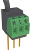
4WFBS120, 4WFBS350, 4WFBS1K 4 Wire Full Bridge Terminal Input Modules (TIM) Datalogger Vx H H H L or AG R2 RD L R1 G or G Shield Jumper Wire Gauge FIGURE 4.2-2. Wiring for 2-wire gauges 4.2.2 Two Wire ¼ Bridge use with Multiplexers and Equations The equations to resolve the strain, - Campbell Scientific 4WFBS1K | 4WFBS120, 4WFBS350, 4WFBS1K 4 Wire Full Bridge Ter - Page 25
4WFBS120, 4WFBS350, 4WFBS1K 4 Wire Full Bridge Terminal Input Modules (TIM) Another temperature induced error in a quarter bridge strain circuit is due to the Temperature Coefficient of Resistance (TCR) of the completion resistor in the arm opposite the strain gauge. The 4WFBS TIMs use a high - Campbell Scientific 4WFBS1K | 4WFBS120, 4WFBS350, 4WFBS1K 4 Wire Full Bridge Ter - Page 26
4WFBS120, 4WFBS350, 4WFBS1K 4 Wire Full Bridge Terminal Input Modules (TIM) The 4WFBS modules can support quarter bridge strain circuits using either the completion resistor built into the TIM, or a user supplied "dummy" strain gauge, for the Wheatstone Bridge arm's resistive - Campbell Scientific 4WFBS1K | 4WFBS120, 4WFBS350, 4WFBS1K 4 Wire Full Bridge Ter - Page 27
4WFBS120, 4WFBS350, 4WFBS1K 4 Wire Full Bridge Terminal Input Modules (TIM) With either circuit, one lead leg, L1 or L3, is in one of the two opposing arms of the Wheatstone bridge. It is important that the gage be wired such, and that these two leads be the same length, diameter and wire type. It - Campbell Scientific 4WFBS1K | 4WFBS120, 4WFBS350, 4WFBS1K 4 Wire Full Bridge Ter - Page 28
4WFBS120, 4WFBS350, 4WFBS1K 4 Wire Full Bridge Terminal Input Modules (TIM) 4.4.1.1 Mathematical Lead Compensation Circuit and Equations If the lead resistance is known, the sensitivity error can be mathematically corrected for by multiplying the output by a simple factor (1+RL/RG) where RL is the - Campbell Scientific 4WFBS1K | 4WFBS120, 4WFBS350, 4WFBS1K 4 Wire Full Bridge Ter - Page 29
Lead Compensation Programs Example Program 4.6. CR9000X ¼ Bridge Strain with zero offset and Lead Compensation This program starts with Example Program 4.2 and adds instructions to mathematically compensate for the leads resistances effects on the Gauge Factor (sensitivity effect). Added - Campbell Scientific 4WFBS1K | 4WFBS120, 4WFBS350, 4WFBS1K 4 Wire Full Bridge Ter - Page 30
4WFBS120, 4WFBS350, 4WFBS1K 4 Wire Full Bridge Terminal Input Modules (TIM) BeginProg 'Program begins here GF(1) = 2.1 : GF(2) = 2.2 : GF(3) = 2.3 'Initialize gauge factors for Strain( ) LeadLength(1) = 1.25 ' load lead lengths (100s of feet) LeadLength(2) = 1.50 LeadLength(3) = 2.00 - Campbell Scientific 4WFBS1K | 4WFBS120, 4WFBS350, 4WFBS1K 4 Wire Full Bridge Ter - Page 31
4WFBS120, 4WFBS350, 4WFBS1K 4 Wire Full Bridge Terminal Input Modules (TIM) Example Program 4.7. CR10X ¼ Bridge Strain with 16 reps, using multiplexer with zero offset and Lead Compensation Calculations using Lead resistance Addr 1 2 3 4 5 6 7 8 9 10 11 12 13 14 15 16 17 18 19 20 21 22 23 24 25 26 - Campbell Scientific 4WFBS1K | 4WFBS120, 4WFBS350, 4WFBS1K 4 Wire Full Bridge Ter - Page 32
4WFBS120, 4WFBS350, 4WFBS1K 4 Wire Full Bridge Terminal Input Modules (TIM) ;{CR10X} ;16SGMux.CSI ;This program calculates the strain for 16 quarter strain bridges using4 wire bridge completion modules. ; It takes into account the sensitivity changes due to lead length resistance. ;(1) Sensors: - Campbell Scientific 4WFBS1K | 4WFBS120, 4WFBS350, 4WFBS1K 4 Wire Full Bridge Ter - Page 33
4WFBS120, 4WFBS350, 4WFBS1K 4 Wire Full Bridge Terminal Input Modules (TIM) 11: Z=X-Y (P35) ; 1: 1 -- X Loc [ mVPerVG01 ] 2: 17 -- Y Loc [ mVPerVZ01 ] 3: 33 Z Loc [ Vr_1 ] 12: Z=X*F (P37) 1: 33 X Loc [ Vr_1 ] 2: -2 F 3: 34 Z Loc [ One_2Vr ] 13: Z=X+F (P34) 1: 34 X Loc [ One_2Vr ] 2: 1000 F 3: 34 Z - Campbell Scientific 4WFBS1K | 4WFBS120, 4WFBS350, 4WFBS1K 4 Wire Full Bridge Ter - Page 34
4WFBS120, 4WFBS350, 4WFBS1K 4 Wire Full Bridge Terminal Input Modules (TIM) 5: Bulk Load (P65) 1: 5 F ; 2: 9 F ; 3: 12 F ; 4: 4 F ; 5: 8 F ; 6: 2 F ; 7: 8 F ; 8: 9 F ; 9: 78 Loc [ LeadFt09 ] 6: Beginning of Loop (P87) ; 1: 0 Delay 2: 16 Loop Count 7: Z=X*Y (P36) 1: 70 -- X Loc [ LeadFt01 ] 2: 69 Y - Campbell Scientific 4WFBS1K | 4WFBS120, 4WFBS350, 4WFBS1K 4 Wire Full Bridge Ter - Page 35
4WFBS120, 4WFBS350, 4WFBS1K 4 Wire Full Bridge Terminal Input Modules (TIM) 7: 350 8: 350 9: 126 F ; F ; Loc [ G09Ohms ] Gage15 Gage16 13: Z=F (P30) ; 1: 4 F 2: 3 Exponent of 10 3: 68 Z Loc [ Number4e3 ] 14: Beginning of Loop (P87) ; 1: 0 Delay 2: 16 Loop Count Load in the large number, 4000.0 - Campbell Scientific 4WFBS1K | 4WFBS120, 4WFBS350, 4WFBS1K 4 Wire Full Bridge Ter - Page 36
4WFBS120, 4WFBS350, 4WFBS1K 4 Wire Full Bridge Terminal Input Modules (TIM) 31: Sample (P70)^16425 1: 16 Reps 2: 52 Loc [ uStrain01 ] 32: Do (P86) 1: 20 Set Output Flag Low (Flag 0) 33: End (P95) End Program 4.4.2 Shunt Calibration Lead Compensation for 3-Wire, ¼ Bridge Strain NOTE Although the - Campbell Scientific 4WFBS1K | 4WFBS120, 4WFBS350, 4WFBS1K 4 Wire Full Bridge Ter - Page 37
4WFBS120, 4WFBS350, 4WFBS1K 4 Wire Full Bridge Terminal Input Modules (TIM) R2= 1KΩ RD - + RL RL R1= 1KΩ RL RS Gauge FIGURE 4.4-2. Shunting remotely across active gauge RL represents the line resistances. RD is the resistor in the arm next to the active gage which has a resistance equal to - Campbell Scientific 4WFBS1K | 4WFBS120, 4WFBS350, 4WFBS1K 4 Wire Full Bridge Ter - Page 38
System. It is included here mainly for reference and for users with our older loggers that are not supported by the Calibration Wizard and higher end instructions. The Calibration Wizard utility which is installed with CSI's software packages greatly simplifies the calibration process. The premise - Campbell Scientific 4WFBS1K | 4WFBS120, 4WFBS350, 4WFBS1K 4 Wire Full Bridge Ter - Page 39
4WFBS120, 4WFBS350, 4WFBS1K 4 Wire Full Bridge Terminal Input Modules (TIM) If shunting across the active gauge, the resistance of the active arm will decrease, reducing the output from the Wheatstone bridge simulating a compressive or negative strain. If shunting across the dummy resistor, the - Campbell Scientific 4WFBS1K | 4WFBS120, 4WFBS350, 4WFBS1K 4 Wire Full Bridge Ter - Page 40
Zero and Shunt Calibration This example program starts out with Example Program 4.2 and adds instructions to perform a Shunt calibration. Added instructions are highlighted. A FieldCalStrain instruction takes care of the underlying math for the Shunt Calibration. Use the Calibration Wizard utility - Campbell Scientific 4WFBS1K | 4WFBS120, 4WFBS350, 4WFBS1K 4 Wire Full Bridge Ter - Page 41
4WFBS120, 4WFBS350, 4WFBS1K 4 Wire Full Bridge Terminal Input Modules (TIM) BeginProg GF(1) = 2.1 : GF(2) = 2.2 ZReps = 3 : ZIndex = 1 For I = 1 To 3 GF_Adjusted(I) = GF(I) Next I ZReps = 3 : ZIndex = 1 LoadFieldCal(True) : GF(3) = 2.3 'Program begins here 'Initialize gauge factors for Strain( ) - Campbell Scientific 4WFBS1K | 4WFBS120, 4WFBS350, 4WFBS1K 4 Wire Full Bridge Ter - Page 42
4WFBS120, 4WFBS350, 4WFBS1K 4 Wire Full Bridge Terminal Input Modules (TIM) In this circuit, R1 and R2 are 1000 ohm resistors making up the back plane of the Wheatstone bridge, as is done in the TIM design. RD is the complementary resistor that has a nominal resistance of the un-strained gage. The - Campbell Scientific 4WFBS1K | 4WFBS120, 4WFBS350, 4WFBS1K 4 Wire Full Bridge Ter - Page 43
units allow the result to be a larger number easier for the datalogger to display and store (see data format discussion in the datalogger manual). The output is a ratio because: 1) the datalogger's ratio metric measurement technique allows this ratio to be more accurate than the measurement of the - Campbell Scientific 4WFBS1K | 4WFBS120, 4WFBS350, 4WFBS1K 4 Wire Full Bridge Ter - Page 44
4WFBS120, 4WFBS350, 4WFBS1K 4 Wire Full Bridge Terminal Input Modules (TIM) Subtracting the unstrained (zero) result from the strained result gives Vr : Vr = ⎜⎛ Vout ⎝ Vin ⎟⎞ ⎠ strained − ⎜⎛ Vout ⎟⎞ ⎝ Vin ⎠ unstrained = Rg + ΔRg − Rg RD + Rg + ΔRg RD + Rg 4.5.4 ( ) ( ) = RD × ΔRg RD + Rg + - Campbell Scientific 4WFBS1K | 4WFBS120, 4WFBS350, 4WFBS1K 4 Wire Full Bridge Ter - Page 45
- Campbell Scientific 4WFBS1K | 4WFBS120, 4WFBS350, 4WFBS1K 4 Wire Full Bridge Ter - Page 46
Campbell Scientific Companies Campbell Scientific, Inc. (CSI) 815 West 1800 North Logan, Utah 84321 UNITED STATES www.campbellsci.com • [email protected] Campbell Scientific Africa Pty. Ltd. (CSAf) PO Box 2450 Somerset West 7129 SOUTH AFRICA www.csafrica.co.za • [email protected] Campbell
-
 1
1 -
 2
2 -
 3
3 -
 4
4 -
 5
5 -
 6
6 -
 7
7 -
8
-
9
-
10
-
11
-
12
-
13
-
14
-
15
-
16
-
17
-
18
-
19
-
20
-
21
-
22
-
23
-
24
-
25
-
26
-
27
-
28
-
29
-
30
-
31
-
32
-
33
-
34
-
35
-
36
-
37
-
38
-
39
-
40
-
41
-
42
-
43
-
44
-
45
-
46
 |
 |

4WFBS120, 4WFBS350, 4WFBS1K
4 Wire Full Bridge Terminal
Input Modules
Revision: 3/12
Copyright © 1996-2010
Campbell Scientific, Inc.