Campbell Scientific 4WFBS1K 4WFBS120, 4WFBS350, 4WFBS1K 4 Wire Full Bridge Ter - Page 23
Quarter Bridge Strain with 2 Wire Element
 |
View all Campbell Scientific 4WFBS1K manuals
Add to My Manuals
Save this manual to your list of manuals |
Page 23 highlights
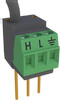
4WFBS120, 4WFBS350, 4WFBS1K 4 Wire Full Bridge Terminal Input Modules (TIM) 4.2 Quarter Bridge Strain with 2 Wire Element NOTE Although a two wire gage can be used with the 4WFBS TIM, due to the issues outlined in Section 4.4.3, it is not recommended. An exception may be applications with short leads in a stable temperature environment. A 2-wire quarter bridge strain circuit is shown in figure 4.2-1. R2=1KΩ Excite V - R1=1KΩ RD + R4=Gauge FIGURE 4.2-1. Two wire quarter bridge strain circuit In this circuit, R1 and R2 are 1000 ohm resistors making up the back plane of the Wheatstone bridge, as is done in the TIM design. RD is the complementary resistor, or Dummy Resistor, that has a nominal resistance of the un-strained gage. The 4th resistive element is the active strain gage. Strain gages are available in nominal resistances of 120, 350, and 1000 ohms. The 4WFBS model must match the nominal resistance of the gage (e.g., the 4WFBS120 is used with a 120 ohm strain gage). As can be seen in Figure 4.2-1, both sensor leads are in the same arm of the Wheatstone bridge. Not only does this affect the sensitivity of the gage, the output from this circuit will include temperature induced line resistance errors. See Section 4.4.3, Lead Compensation using ¼ Bridge Strain with 2 Wire Element for more information on issues with using 2 wire gages. 4.2.1 Quarter Bridge Strain with 2 Wire Element Wiring To use a two wire element strain gauge with the 4WFBS TIM requires a jumper wire be placed between the H and L terminal of the TIM module as shown in Figure 4.2-2. 17
-
 1
1 -
2
-
3
-
4
-
5
-
6
-
7
-
8
-
9
-
10
-
11
-
12
-
13
-
14
-
15
-
16
-
17
-
 18
18 -
 19
19 -
 20
20 -
 21
21 -
 22
22 -
 23
23 -
 24
24 -
 25
25 -
 26
26 -
 27
27 -
 28
28 -
29
-
30
-
31
-
32
-
33
-
34
-
35
-
36
-
37
-
38
-
39
-
40
-
41
-
42
-
43
-
44
-
45
-
46
 |
 |
