Campbell Scientific 4WFBS1K 4WFBS120, 4WFBS350, 4WFBS1K 4 Wire Full Bridge Ter - Page 26
Quarter Bridge Strain with Dummy Gauge Wiring Setup
 |
View all Campbell Scientific 4WFBS1K manuals
Add to My Manuals
Save this manual to your list of manuals |
Page 26 highlights
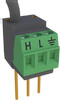
4WFBS120, 4WFBS350, 4WFBS1K 4 Wire Full Bridge Terminal Input Modules (TIM) The 4WFBS modules can support quarter bridge strain circuits using either the completion resistor built into the TIM, or a user supplied "dummy" strain gauge, for the Wheatstone Bridge arm's resistive element opposite of the active strain gauge in the bridge. Wiring circuits using a dummy gage are covered in Section 4.3.1. 4.3.1 Quarter Bridge Strain with Dummy Gauge Wiring Setup Figure 4.3-2 illustrates the wiring of the strain gage with a dummy gage to the 4WFBS module, as well as the wiring of the module to the datalogger. This shows the dummy gauge out at the remote site along with the active gage. This is the best setup to achieve the best compensation for the apparent strain and gauge factor variance due to temperature fluctuations, as it will be easier to keep the temperature of the two gages equivalent. FIGURE 4.3-2. ¼ bridge strain with remote dummy gauge Figure 4.3-3 illustrates the wiring of the strain gage to the 4WFBS module with the Dummy gauge at the logger location. Apparent strain errors could result because of temperature variances between the two gauges with this setup. This circuit is still utilized in some applications for ease of Shunt calibration (can shunt across Dummy gage at logger location rather than at the remote gauge location). Also an existing, standard 3-wire ¼ Bridge strain circuit can easily be transformed into this circuit. If large temperature variances will exist between the active gage and the dummy gage located at the datalogger, using the 4WFBS completion resistor can result in lower temperature induced errors. FIGURE 4.3-3. ¼ bridge strain with dummy gauge at datalogger 20
-
 1
1 -
2
-
3
-
4
-
5
-
6
-
7
-
8
-
9
-
10
-
11
-
12
-
13
-
14
-
15
-
16
-
17
-
18
-
19
-
20
-
 21
21 -
 22
22 -
 23
23 -
 24
24 -
 25
25 -
 26
26 -
 27
27 -
 28
28 -
 29
29 -
 30
30 -
 31
31 -
32
-
33
-
34
-
35
-
36
-
37
-
38
-
39
-
40
-
41
-
42
-
43
-
44
-
45
-
46
 |
 |
