Campbell Scientific 4WFBS1K 4WFBS120, 4WFBS350, 4WFBS1K 4 Wire Full Bridge Ter - Page 38
WFBS120, 4WFBS350, 4WFBS1K, Wire Full Bridge Terminal Input Modules TIM, Wiring
 |
View all Campbell Scientific 4WFBS1K manuals
Add to My Manuals
Save this manual to your list of manuals |
Page 38 highlights
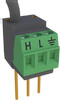
4WFBS120, 4WFBS350, 4WFBS1K 4 Wire Full Bridge Terminal Input Modules (TIM) NOTE It should be noted that a shunt resistor should not be connected across the active gauge's leads back at the completion portion of the Wheatstone Bridge, as this would not correctly account for the leads resistances. If performing a shunt back at the instrumentation location, it must be done across the Dummy Resistor as shown in figure 4.4-3. The 4WFBS TIM modules include 2 gold plated, shunt pin receptacles to facilitate easy access to the internal dummy resistor. These receptacles, which accept 0.015 to 0.025 inch diameter pins, are depicted in figure 4.4-4. Datalogger 4WFBSXXX TIM VX or EX Shunt Receptacle H Active Gauge RD R2 =1KΩ R1=1KΩ L AG or G Shunt Receptacle FIGURE 4.4-4. Wiring for shunt across dummy resistor To shunt the dummy resistor, simply connect the resistor across the two gold plated shunt receptacles so that it is in parallel with the dummy resistor. 4.4.2.2 Math for Shunt Calibration of 3-Wire, ¼ Bridge Strain Circuits NOTE The math in this section is done automatically for the user by the Datalogger's Operating System. It is included here mainly for reference and for users with our older loggers that are not supported by the Calibration Wizard and higher end instructions. The Calibration Wizard utility which is installed with CSI's software packages greatly simplifies the calibration process. The premise is the same when shunting across either arm. The shunted arm undergoes a reduction in resistance creating a simulated strain. The change in resistance of the shunted arm is given by Equation 4.4.9: ΔR = − RG RG RG + RS 4.4.9 Variable definitions: ΔR = Change in arm resistance (ohms) RG = Nominal gauge resistance (ohms) RS = Shunt resistor resistance (ohms) 32
-
 1
1 -
2
-
3
-
4
-
5
-
6
-
7
-
8
-
9
-
10
-
11
-
12
-
13
-
14
-
15
-
16
-
17
-
18
-
19
-
20
-
21
-
22
-
23
-
24
-
25
-
26
-
27
-
28
-
29
-
30
-
31
-
32
-
 33
33 -
 34
34 -
 35
35 -
 36
36 -
 37
37 -
 38
38 -
 39
39 -
 40
40 -
 41
41 -
 42
42 -
 43
43 -
44
-
45
-
46
 |
 |
