Campbell Scientific 4WFBS1K 4WFBS120, 4WFBS350, 4WFBS1K 4 Wire Full Bridge Ter - Page 27
Quarter Bridge Strain Lead Resistance Compensation
 |
View all Campbell Scientific 4WFBS1K manuals
Add to My Manuals
Save this manual to your list of manuals |
Page 27 highlights
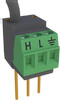
4WFBS120, 4WFBS350, 4WFBS1K 4 Wire Full Bridge Terminal Input Modules (TIM) With either circuit, one lead leg, L1 or L3, is in one of the two opposing arms of the Wheatstone bridge. It is important that the gage be wired such, and that these two leads be the same length, diameter and wire type. It is preferable to use a twisted pair for these two wires so that they will undergo the same temperature and electromagnetic field variations. With this configuration, changes in wire resistance due to temperature occur equally in both arms of the bridge with negligible effect on the output from the bridge. 4.3.2 Quarter Bridge Strain with Dummy Gauge Calculations The calculations for this bridge setup are the same as for the 3-Wire Quarter Bridge circuit. See Section 4.1.2 Quarter Bridge Strain with3 Wire Element Calculations for details. 4.3.3 Quarter Bridge Strain with Dummy Gauge Example Programs The programming for this bridge setup is the same as for the 3-Wire Quarter Bridge circuit. See Section 4.1.3 Quarter Bridge Strain with3 Wire Program Examples for details. 4.4 Quarter Bridge Strain Lead Resistance Compensation When using quarter bridge strain (full bridge with one active element) with long lead lengths, errors can be introduced due to the resistance of the leads. This section covers both mathematical and Shunt Calibration methods used to rectify these errors. The techniques covered in the section can be used with circuits using a 4WFBS's completion resistor or a dummy gauge for the resistive element in the third arm of the Wheatstone Bridge (arm opposite of active gauge). The only difference is that when using a dummy gauge, the 4WFBS module's gold shunt receptacles cannot be used. These receptacles are connected to the dummy resistor supplied by the 4WFBS module. One potential error with long leads is due to the leads' resistance change from temperature fluctuations. When using a three wire strain gauge, wired as depicted in Figure 4.1-2 3-Wire ¼ Bridge Strain Wiring, with the three leads all the same length and laid out together (all three experience the same temperature swings), the leads' resistance changes are self compensating. It is preferable to use a twisted pair for the two wires (L and G) carrying the current so that they definitely undergo the same temperature and electromagnetic field variations. With this configuration, changes in wire resistance due to temperature occur equally in both arms of the bridge with negligible effect on the output from the bridge. Another error that is introduced when using long leads, is a sensitivity reduction of the system. There are two methods to rectify this error. The first is mathematical. The second is to perform a shunt calibration. Sections 4.4.1 and 4.4.2 cover these methods for ¼ Bridge Strain circuits. 4.4.1 Mathematical Lead Compensation for 3-Wire, ¼ Bridge Strain The same equations pertain whether a completion (dummy) resistor or a dummy gauge is used to complete the third arm of the Wheatstone Bridge. So the material in this section is relevant for wiring setups shown in Figures 4.1-2, 4.3-2, and 4.3-3. The math and the programs used would be identical for all three of these circuits. 21
-
 1
1 -
2
-
3
-
4
-
5
-
6
-
7
-
8
-
9
-
10
-
11
-
12
-
13
-
14
-
15
-
16
-
17
-
18
-
19
-
20
-
21
-
 22
22 -
 23
23 -
 24
24 -
 25
25 -
 26
26 -
 27
27 -
 28
28 -
 29
29 -
 30
30 -
 31
31 -
 32
32 -
33
-
34
-
35
-
36
-
37
-
38
-
39
-
40
-
41
-
42
-
43
-
44
-
45
-
46
 |
 |
