Campbell Scientific WINDSONIC1 WINDSONIC 2-D Sonic Wind Sensors - Page 11
WindSonic Two-Dimensional Sonic Anemometer, WindSonic mounted on a CM202 using pn 17837
 |
View all Campbell Scientific WINDSONIC1 manuals
Add to My Manuals
Save this manual to your list of manuals |
Page 11 highlights
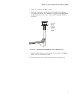
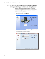
WindSonic Two-Dimensional Sonic Anemometer 5. Mount the crossarm to the tripod or tower. 6. Orient the WindSonic so that the colored North marker arrows point to True North (see FIGURE 4-1). Appendix A contains detailed information on determining True North using a compass and the magnetic declination for the site. Colored North Marker Arrows Pointing North FIGURE 4-1. WindSonic mounted on a CM202 using pn 17837 7. Route the sensor cable along the underside of the crossarm to the tripod or tower, and to the instrument enclosure. 8. Secure the cable to the crossarm and tripod or tower using cable ties. 3
-
 1
1 -
2
-
3
-
4
-
5
-
 6
6 -
 7
7 -
 8
8 -
 9
9 -
 10
10 -
 11
11 -
 12
12 -
 13
13 -
 14
14 -
 15
15 -
 16
16 -
17
-
18
-
19
-
20
-
21
-
22
-
23
-
24
-
25
-
26
-
27
-
28
-
29
-
30
-
31
-
32
-
33
-
34
-
35
-
36
-
37
-
38
-
39
-
40
-
41
-
42
-
43
-
44
-
45
-
46
 |
 |

WindSonic Two-Dimensional Sonic Anemometer
5.
Mount the crossarm to the tripod or tower.
6.
Orient the WindSonic so that the colored North marker arrows point to
True North (see FIGURE 4-1).
Appendix A contains detailed information
on determining True North using a compass and the magnetic declination
for the site.
FIGURE 4-1.
WindSonic mounted on a CM202 using pn 17837
Colored
North
Marker
Arrows
Pointing
North
7.
Route the sensor cable along the underside of the crossarm to the tripod or
tower, and to the instrument enclosure.
8.
Secure the cable to the crossarm and tripod or tower using cable ties.
3