Canon LV-7280 User Manual - Page 13
(3) Part Names of the Projector, Front/Top, Rear
 |
View all Canon LV-7280 manuals
Add to My Manuals
Save this manual to your list of manuals |
Page 13 highlights
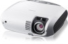
Part Names of the Projector Front/Top Zoom Lever (See page 29) Controls (See page 5) 1. Introduction Focus Ring (See page 29) Remote sensor (See page 9) Adjustable Tilt Foot Lock Button (See page 30) Adjustable Tilt Foot (See page 30) Lens * This security slot supports the MicroSaver ® Security System. Built-in Security Slot ( )* Ventilation (inlet) / Filter Cover (See page 69) Do not block this vent. Troubles or fire can result. Lens Cover Be sure to remove the lens cover during projection. The cap can deform or fire can occur. Rear Lamp Cover (See page 72) Terminal Panel (See page 6) Monaural Speaker (7W) Ventilation (inlet) / Filter Cover (See page 69) Do not block this vent. Troubles or fire can result. Carrying Handle Main Power Switch When you plug the supplied power cord into an active wall outlet and turn on the Main Power, the POWER indicator turns orange and the projector is in standby mode. (See page 24) Ventilation (outlet) Heated air is exhausted from here. Do not block this vent. Troubles or fire can result. Rear Foot Spacer (black rubber) A spacer is provided for leveling the projector. To fine-adjust the height of the rear foot, remove the spacer and rotate the rear foot to the desired height. AC Input Connect the supplied power cord's two-pin plug here, and plug the other end into an active wall outlet. (See page 23) 4
-
 1
1 -
2
-
3
-
4
-
5
-
6
-
7
-
 8
8 -
 9
9 -
 10
10 -
 11
11 -
 12
12 -
 13
13 -
 14
14 -
 15
15 -
 16
16 -
 17
17 -
 18
18 -
19
-
20
-
21
-
22
-
23
-
24
-
25
-
26
-
27
-
28
-
29
-
30
-
31
-
32
-
33
-
34
-
35
-
36
-
37
-
38
-
39
-
40
-
41
-
42
-
43
-
44
-
45
-
46
-
47
-
48
-
49
-
50
-
51
-
52
-
53
-
54
-
55
-
56
-
57
-
58
-
59
-
60
-
61
-
62
-
63
-
64
-
65
-
66
-
67
-
68
-
69
-
70
-
71
-
72
-
73
-
74
-
75
-
76
-
77
-
78
-
79
-
80
-
81
-
82
-
83
-
84
-
85
-
86
-
87
-
88
-
89
-
90
-
91
-
92
-
93
-
94
-
95
-
96
 |
 |
