Casio CTK7000 User Guide - Page 40
Using the Sliders to Change Parameter Settings
 |
View all Casio CTK7000 manuals
Add to My Manuals
Save this manual to your list of manuals |
Page 40 highlights
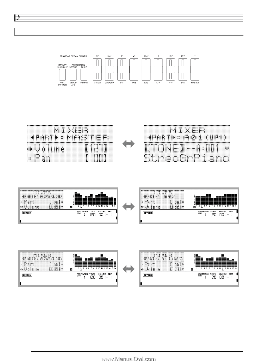
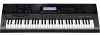
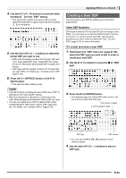
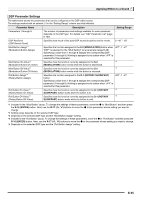
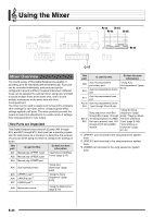
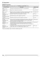
Using the Mixer Using the Sliders to Change Parameter Settings While the mixer screen is displayed, use sliders D-4 (1/9/EXT) to D-12 (MASTER) to change the displayed parameter settings. The D-1 (PART/COMMON), D-2 (GROUP A/B) and D-3 (1-8/9-16) buttons are used to specify the parts that correspond to sliders D-4 (1/9/EXT) to D-11 (8/16). D-1 D-2 D-3 D-4 D-5 D-6 D-7 D-8 D-9 D-10 D-11 D-12 The following describes the operation of these buttons and sliders while the mixer screen is displayed. ● D-1 (PART/COMMON) button: Each press toggles the mixer screen between master parameter settings (MASTER) and the settings of one of the part (A01 through A16, B01 through B16) parameters. ● D-2 (GROUP A/B) button: Each press toggles the part parameter setting screen between one of the parts in group L (A01 through A16) and one of the parts in group M (B01 through B16). ● D-3 (1-8/9-16) button: Each press toggles the parts that correspond to parameter operations by sliders D-4 (1/9/EXT) to D-11 (8/6) between A01 through A08 (or B01 through B08) and A09 through A16 (or B09 through B16). E-38
-
 1
1 -
2
-
3
-
4
-
5
-
6
-
7
-
8
-
9
-
10
-
11
-
12
-
13
-
14
-
15
-
16
-
17
-
18
-
19
-
20
-
21
-
22
-
23
-
24
-
25
-
26
-
27
-
28
-
29
-
30
-
31
-
32
-
33
-
34
-
 35
35 -
 36
36 -
 37
37 -
 38
38 -
 39
39 -
 40
40 -
 41
41 -
 42
42 -
 43
43 -
 44
44 -
 45
45 -
46
-
47
-
48
-
49
-
50
-
51
-
52
-
53
-
54
-
55
-
56
-
57
-
58
-
59
-
60
-
61
-
62
-
63
-
64
-
65
-
66
-
67
-
68
-
69
-
70
-
71
-
72
-
73
-
74
-
75
-
76
-
77
-
78
-
79
-
80
-
81
-
82
-
83
-
84
-
85
-
86
-
87
-
88
-
89
-
90
-
91
-
92
-
93
-
94
-
95
-
96
-
97
-
98
-
99
-
100
-
101
-
102
-
103
-
104
-
105
-
106
-
107
-
108
-
109
-
110
-
111
-
112
-
113
-
114
-
115
-
116
-
117
-
118
-
119
-
120
-
121
-
122
-
123
-
124
-
125
-
126
-
127
-
128
-
129
-
130
-
131
-
132
-
133
-
134
-
135
-
136
-
137
-
138
-
139
-
140
-
141
-
142
-
143
-
144
-
145
-
146
-
147
-
148
-
149
-
150
-
151
-
152
-
153
-
154
-
155
-
156
-
157
-
158
-
159
-
160
-
161
-
162
-
163
-
164
-
165
-
166
-
167
-
168
 |
 |