Cisco 7206 Installation Guide - Page 91
Connecting DC-Input Power, Step 5
 |
UPC - 746320703879
View all Cisco 7206 manuals
Add to My Manuals
Save this manual to your list of manuals |
Page 91 highlights
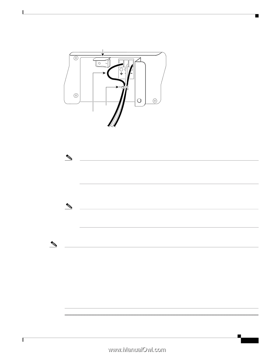
Chapter 3 Installing the Cisco 7206 Figure 3-23 Connecting DC-Input Power Power switch Connecting Power H8622 Cable tie Ground lead service loop DC power leads Step 5 Insert the stripped end of the +V lead all the way into the +V lead receptacle and tighten the receptacle screw using the same 3/16-inch flat-blade screwdriver. Repeat this step for the -V lead. Note Make sure the entire stripped end of each lead is inserted all the way into its receptacle. If any exposed wire at the stripped end of a lead is visible after inserting the lead into its receptacle, remove the lead from the receptacle, use the wire stripper to cut the stripped end of the lead, and repeat Step 2 through Step 5. Step 6 After tightening the receptacle screw for the ground, +V, and -V DC-input leads, use the cable tie (see Figure 3-23) to secure the three leads to the power supply faceplate. Note When securing the ground, +V, and -V DC-input leads to the power supply faceplate, leave a small service loop in the ground lead to ensure that the ground lead is the last lead to disconnect from the power supply if a great deal of strain is placed on all three leads (refer to Figure 3-23). Step 7 Switch the circuit breaker to the ON position. Note Each DC-input power supply operating at 24 VDC requires a minimum of 19A service. Each DC-input power supply operating at 48 VDC requires a minimum of 13A service. Each DC-input power supply operating at 60 VDC requires a minimum of 8A service. The preceding values are absolute maximum values. Typical system configurations use substantially less. To obtain typical values for your configuration, contact your Cisco sales representative. This product relies on the building's installation for short-circuit (overcurrent) protection. Ensure that a listed and certified fuse or circuit breaker, 35A minimum 60 VDC, is used on all current-carrying conductors. Site wiring and circuit breakers need to be sized to accommodate the maximum values for safety reasons. OL-5102-02 Cisco 7206 Installation and Configuration Guide 3-23
-
 1
1 -
2
-
3
-
4
-
5
-
6
-
7
-
8
-
9
-
10
-
11
-
12
-
13
-
14
-
15
-
16
-
17
-
18
-
19
-
20
-
21
-
22
-
23
-
24
-
25
-
26
-
27
-
28
-
29
-
30
-
31
-
32
-
33
-
34
-
35
-
36
-
37
-
38
-
39
-
40
-
41
-
42
-
43
-
44
-
45
-
46
-
47
-
48
-
49
-
50
-
51
-
52
-
53
-
54
-
55
-
56
-
57
-
58
-
59
-
60
-
61
-
62
-
63
-
64
-
65
-
66
-
67
-
68
-
69
-
70
-
71
-
72
-
73
-
74
-
75
-
76
-
77
-
78
-
79
-
80
-
81
-
82
-
83
-
84
-
85
-
 86
86 -
 87
87 -
 88
88 -
 89
89 -
 90
90 -
 91
91 -
 92
92 -
 93
93 -
 94
94 -
 95
95 -
 96
96 -
97
-
98
-
99
-
100
-
101
-
102
-
103
-
104
-
105
-
106
-
107
-
108
-
109
-
110
-
111
-
112
-
113
-
114
-
115
-
116
-
117
-
118
-
119
-
120
-
121
-
122
-
123
-
124
-
125
-
126
-
127
-
128
-
129
-
130
-
131
-
132
-
133
-
134
-
135
-
136
-
137
-
138
-
139
-
140
-
141
-
142
-
143
-
144
-
145
-
146
-
147
-
148
-
149
-
150
 |
 |