Cisco CISCO815-VPN/K9 Hardware Installation Guide - Page 20
Cisco 804 Router Back Panel, TO HUB/TO PC
 |
UPC - 882658121388
View all Cisco CISCO815-VPN/K9 manuals
Add to My Manuals
Save this manual to your list of manuals |
Page 20 highlights
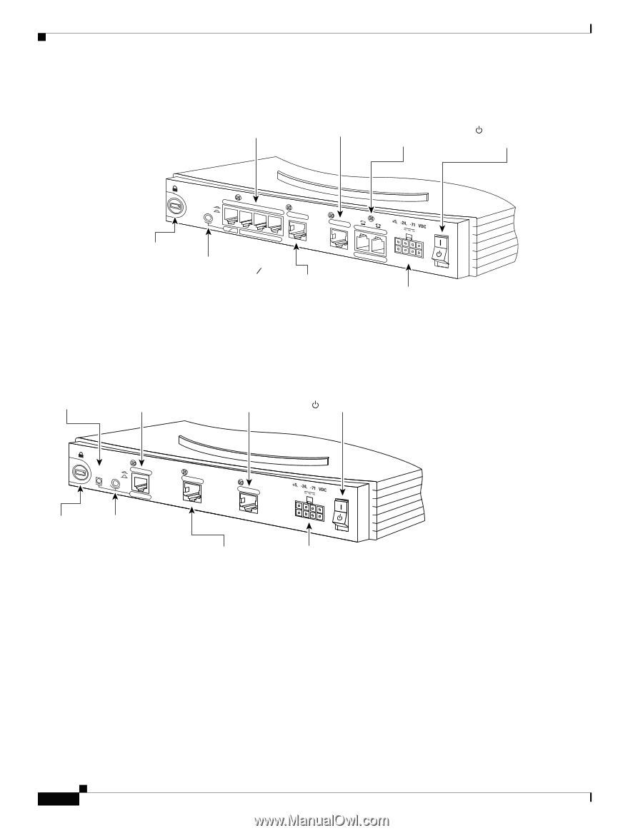
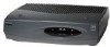
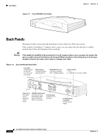
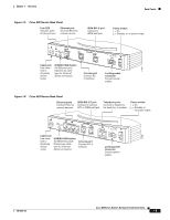
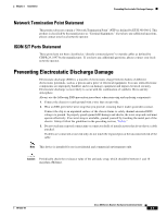
Back Panels Chapter 1 Overview Figure 1-7 Cisco 804 Router Back Panel Ethernet ports Connect Ethernet network devices. ISDN BRI U port Connect to ISDN wall jack. Telephone ports Connect to telephone, fax machine, or modem. Power switch l = On. = Standby or no power output. 11669 Cable lock Use cable lock to physically secure router. HUB NO HUB ETHERNET 10 BASE T 0 1 2 3 HUB/NO HUB button (for Ethernet port 0) Determines cable type for Ethernet device connection. Cisco 804 CONSOLE ISDN U Console port Connect PC or terminal. PHONE 1 2 Locking power connector Connect power supply. Figure 1-8 Cisco 802 IDSL Router Back Panel Link LED Indicates state of Ethernet port. Ethernet port Connect Ethernet network device. IDSL port Connect to IDSL wall jack. Power switch l = On. = Standby or no power output. LINK TO TO HUB PC ETHERNET 10 BASE T CONSOLE Cisco 802 IDSL IDSL Cable lock Use cable lock to physically secure router. TO HUB/TO PC (for Ethernet port) Determines cable type for Ethernet device connection. Console port Connect PC or terminal. Locking power connector Connect power supply. 30771 Cisco 800 Series Routers Hardware Installation Guide 1-6 78-5373-04
-
 1
1 -
2
-
3
-
4
-
5
-
6
-
7
-
8
-
9
-
10
-
11
-
12
-
13
-
14
-
 15
15 -
 16
16 -
 17
17 -
 18
18 -
 19
19 -
 20
20 -
 21
21 -
 22
22 -
 23
23 -
 24
24 -
 25
25 -
26
-
27
-
28
-
29
-
30
-
31
-
32
-
33
-
34
-
35
-
36
-
37
-
38
-
39
-
40
-
41
-
42
-
43
-
44
-
45
-
46
-
47
-
48
-
49
-
50
-
51
-
52
-
53
-
54
-
55
-
56
-
57
-
58
-
59
-
60
-
61
-
62
-
63
-
64
-
65
-
66
-
67
-
68
-
69
-
70
 |
 |