Cisco CISCO815-VPN/K9 Hardware Installation Guide - Page 42
Verifying Installation
 |
UPC - 882658121388
View all Cisco CISCO815-VPN/K9 manuals
Add to My Manuals
Save this manual to your list of manuals |
Page 42 highlights
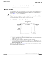
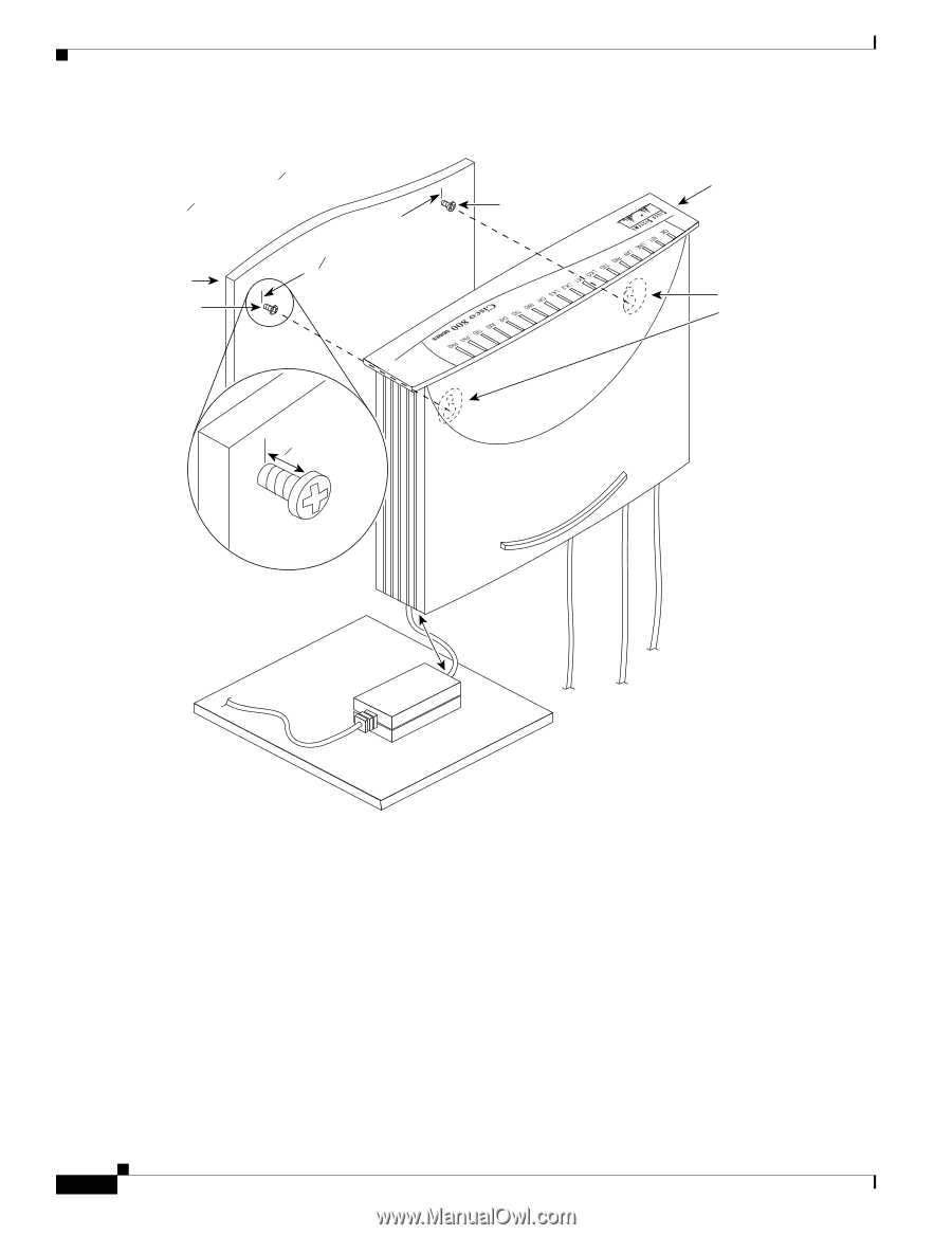
Verifying Installation Figure 2-12 Mounting Router on Wall 1. Secure two screws 7 5 8 inches (19.35 cm) apart in a wall and 1 8 in. (0.32 cm) from the wall. 758 in. (19.35 cm) Wall Wall-mount screw Wall-mount screw Wall 1 8 in. (0.32 cm) Screw Maximum distance 6 ft (18 m) 11672 Chapter 2 Installation Front panel Mounting brackets 2. Hang router on screws. 3. Place power supply on horizontal surface. Verifying Installation Verify the cable connections (links) by checking the LEDs listed in Table 2-4. If the LEDs are not on, see Chapter 3, "Troubleshooting." The LINK LED is on the back panel of Cisco 801 and Cisco 802 routers. 2-20 Cisco 800 Series Routers Hardware Installation Guide 78-5373-04
-
 1
1 -
2
-
3
-
4
-
5
-
6
-
7
-
8
-
9
-
10
-
11
-
12
-
13
-
14
-
15
-
16
-
17
-
18
-
19
-
20
-
21
-
22
-
23
-
24
-
25
-
26
-
27
-
28
-
29
-
30
-
31
-
32
-
33
-
34
-
35
-
36
-
 37
37 -
 38
38 -
 39
39 -
 40
40 -
 41
41 -
 42
42 -
 43
43 -
 44
44 -
 45
45 -
 46
46 -
 47
47 -
48
-
49
-
50
-
51
-
52
-
53
-
54
-
55
-
56
-
57
-
58
-
59
-
60
-
61
-
62
-
63
-
64
-
65
-
66
-
67
-
68
-
69
-
70
 |
 |
2-20
Cisco 800 Series Routers Hardware Installation Guide
78-5373-04
Chapter 2
Installation
Verifying Installation
Figure 2-12
Mounting Router on Wall
Verifying Installation
Verify the cable connections (links) by checking the LEDs listed in
Table 2-4
. If the LEDs are not on,
see Chapter 3, “
Troubleshooting
.”
The LINK LED is on the back panel of Cisco
801 and Cisco
802 routers.
7
in. (19.35 cm)
11672
Wall-mount
screw
Wall-mount
screw
Wall
Mounting
brackets
Front panel
1. Secure two screws 7
inches
(19.35 cm) apart in a wall
and
in. (0.32 cm) from
the wall.
2.
Hang router
on screws.
3. Place power supply
on horizontal surface.
Maximum distance
6 ft (18 m)
5
8
5
8
1
8
Screw
in. (0.32 cm)
1
8
Wall