Cisco CISCO815-VPN/K9 Hardware Installation Guide - Page 21
LEDs, Cisco 804 IDSL Router Back Panel, Table 1-3, LED Functions
 |
UPC - 882658121388
View all Cisco CISCO815-VPN/K9 manuals
Add to My Manuals
Save this manual to your list of manuals |
Page 21 highlights
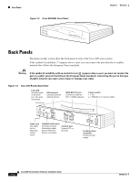
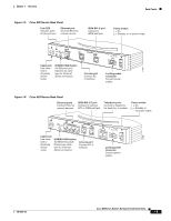
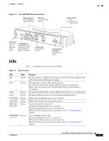
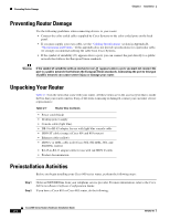
Chapter 1 Overview LEDs Figure 1-9 Cisco 804 IDSL Router Back Panel Ethernet ports Connect Ethernet network devices. IDSL port Connect to IDSL wall jack. Power switch l = On. = Standby or no power output. 30772 Cable lock Use cable lock to physically secure router. TO TO HUB PC ETHERNET 10 BASE T 1 2 3 4 TO HUB/TO PC (for Ethernet port 1) Determines cable type for Ethernet device connection. Cisco 804 IDSL CONSOLE IDSL Console port Connect PC or terminal. Locking power connector Connect power supply. LEDs Table 1-3 summarizes the function of each LED. Table 1-3 LED Functions LED Color OK Green NT1 Green LINE LAN LAN RXD LAN TXD LKØ, LK1, LK2, LK3 Green Green Green Green Green ETHERNET Green 1, 2, 3, 4 Function On when power is supplied to the router and when the router completes the self-test procedure and begins operating. Not applicable for Cisco 801 and 803 routers. On when the internal NT1 and the ISDN switch are synchronized. Blinks when the internal NT1 and the ISDN switch are attempting to synchronize. On when the ISDN interface and the ISDN terminal device are synchronized. On when packets are sent to or received from an Ethernet port. Blinks when an Ethernet port receives a packet. Blinks when an Ethernet port sends a packet. Cisco 803 and 804 routers only. On when the Ethernet device is connected. Off when the Ethernet device is not connected. Blinks when the connection has a problem. See the "Troubleshooting" chapter. Cisco 804 IDSL routers only. On when the Ethernet device is connected. Off when the Ethernet device is not connected. Blinks when the connection has a problem. See the "Troubleshooting" chapter. 78-5373-04 Cisco 800 Series Routers Hardware Installation Guide 1-7
-
 1
1 -
2
-
3
-
4
-
5
-
6
-
7
-
8
-
9
-
10
-
11
-
12
-
13
-
14
-
15
-
 16
16 -
 17
17 -
 18
18 -
 19
19 -
 20
20 -
 21
21 -
 22
22 -
 23
23 -
 24
24 -
 25
25 -
 26
26 -
27
-
28
-
29
-
30
-
31
-
32
-
33
-
34
-
35
-
36
-
37
-
38
-
39
-
40
-
41
-
42
-
43
-
44
-
45
-
46
-
47
-
48
-
49
-
50
-
51
-
52
-
53
-
54
-
55
-
56
-
57
-
58
-
59
-
60
-
61
-
62
-
63
-
64
-
65
-
66
-
67
-
68
-
69
-
70
 |
 |