Cisco PLE300 User Guide - Page 8
Product Overview, Wall-Mounting Placement - adapter
 |
View all Cisco PLE300 manuals
Add to My Manuals
Save this manual to your list of manuals |
Page 8 highlights
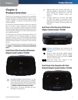
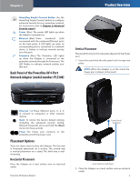
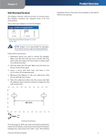
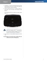
Chapter 2 Wall-Mounting Placement The Adapter has four wall-mount slots on its back panel. The distance between two adjacent slots is 60 mm (2.36 inches). Two screws are needed to mount the Adapter. Suggested Mounting Hardware 2-2.5 mm 4 mm 1-1.5 mm ††Note: Mounting hardware illustrations are not true to scale. NOTE: Linksys is not responsible for damages incurred by insecure wall-mounting hardware. Follow these instructions: 1. Determine where you want to mount the Adapter. Make sure that the wall you use is smooth, flat, dry, and sturdy. Also make sure the location is within reach of an electrical outlet. 2. Drill two holes into the wall. Make sure the holes are 60 mm (2.36 inches) apart. 3. Insert a screw into each hole and leave 3 mm (0.12 inches) of its head exposed. 4. Maneuver the Adapter so the two wall-mount slots line up with the two screws. 5. Place the wall-mount slots over the screws and slide the Adapter down until the screws fit snugly into the wall-mount slots. Product Overview should be 60 mm. Then place the template on the wall to drill precise spacing. 60 mm Wall Mounting Template Print this page at 100% size, and cut along the dotted line. Check the template's accuracy by measuring the distance between the wall-mount slots with a ruler. This distance Powerline AV Network Adapter 5
-
 1
1 -
2
-
 3
3 -
 4
4 -
 5
5 -
 6
6 -
 7
7 -
 8
8 -
 9
9 -
 10
10 -
 11
11 -
 12
12 -
 13
13 -
14
-
15
-
16
-
17
-
18
-
19
-
20
-
21
-
22
-
23
-
24
-
25
-
26
-
27
-
28
-
29
-
30
-
31
 |
 |
