Cisco RV082 Administration Guide - Page 175
Configuring a VPN Tunnel on a Cisco RV0xx Series Router
 |
UPC - 745883556700
View all Cisco RV082 manuals
Add to My Manuals
Save this manual to your list of manuals |
Page 175 highlights
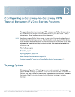
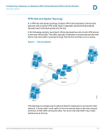
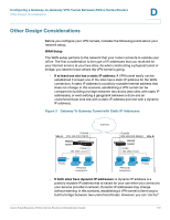
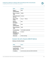
Configuring a Gateway-to-Gateway VPN Tunnel Between RV0xx Series Routers Configuring a VPN Tunnel on a Cisco RV0xx Series Router D Configuring a VPN Tunnel on a Cisco RV0xx Series Router This procedure describes the basic tasks in configuring your router. Example entries are provided on page 176. NOTE • For a hub-and-spoke topology, configure one tunnel between each remote site and the central site. For the scenario illustrated in Figure 1, configure three VPN tunnels on the router at the main site, and configure one VPN tunnel on the router at each remote site. • For a mesh topology, configure multiple tunnels on each router to ensure connectivity between all sites. For the scenario illustrated in Figure 2, configure three VPN tunnels on each router. STEP 1 Connect a computer to your Cisco RV0xx Series router (called Site A in the examples), and start the web-based configuration utility. STEP 2 Click VPN > Gateway to Gateway in the navigation tree. STEP 3 Enter the following information about the tunnel: • Tunnel Name-Enter a name, for your reference. This name will be used on the VPN > Summary page. • Interface-Select the appropriate Interface, WAN1 or WAN2. Note: The Enable check box is unavailable until after you save the configuration. STEP 4 In the Local Group Setup section, enter the following information about this router (Site A): • Local Security Gateway Type-Select IP Only. The WAN IP address of the router will be automatically detected and will appear in the IP Address field. • Local Security Group Type-Select Subnet. Enter the LAN IP Address and the subnet mask. STEP 5 In the Remote Group Setup section, enter the following information about the router at the other end of the tunnel (Site B): • Remote Security Gateway Type-Depending on the type of IP address for the Internet connection, choose one of the following options: - If the remote gateway (Site B) has a static WAN IP address: Select IP Only. Enter the WAN IP Address of the Site B router. Cisco Small Business RV0xx Series Routers Administration Guide 175
-
 1
1 -
2
-
3
-
4
-
5
-
6
-
7
-
8
-
9
-
10
-
11
-
12
-
13
-
14
-
15
-
16
-
17
-
18
-
19
-
20
-
21
-
22
-
23
-
24
-
25
-
26
-
27
-
28
-
29
-
30
-
31
-
32
-
33
-
34
-
35
-
36
-
37
-
38
-
39
-
40
-
41
-
42
-
43
-
44
-
45
-
46
-
47
-
48
-
49
-
50
-
51
-
52
-
53
-
54
-
55
-
56
-
57
-
58
-
59
-
60
-
61
-
62
-
63
-
64
-
65
-
66
-
67
-
68
-
69
-
70
-
71
-
72
-
73
-
74
-
75
-
76
-
77
-
78
-
79
-
80
-
81
-
82
-
83
-
84
-
85
-
86
-
87
-
88
-
89
-
90
-
91
-
92
-
93
-
94
-
95
-
96
-
97
-
98
-
99
-
100
-
101
-
102
-
103
-
104
-
105
-
106
-
107
-
108
-
109
-
110
-
111
-
112
-
113
-
114
-
115
-
116
-
117
-
118
-
119
-
120
-
121
-
122
-
123
-
124
-
125
-
126
-
127
-
128
-
129
-
130
-
131
-
132
-
133
-
134
-
135
-
136
-
137
-
138
-
139
-
140
-
141
-
142
-
143
-
144
-
145
-
146
-
147
-
148
-
149
-
150
-
151
-
152
-
153
-
154
-
155
-
156
-
157
-
158
-
159
-
160
-
161
-
162
-
163
-
164
-
165
-
166
-
167
-
168
-
169
-
 170
170 -
 171
171 -
 172
172 -
 173
173 -
 174
174 -
 175
175 -
 176
176 -
 177
177 -
 178
178 -
 179
179 -
 180
180 -
181
-
182
-
183
-
184
-
185
-
186
-
187
-
188
-
189
-
190
-
191
-
192
-
193
-
194
-
195
-
196
-
197
-
198
-
199
 |
 |