Cisco WAP2000 User Guide - Page 17
Apply, Disabled, untagged - default
 |
UPC - 745883578337
View all Cisco WAP2000 manuals
Add to My Manuals
Save this manual to your list of manuals |
Page 17 highlights
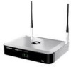
Chapter 5 Advanced Configuration Access Point address, the Broadcast destination addresses, a time stamp, Delivery Traffic Indicator Maps, and the Traffic Indicator Message (TIM). The default is 100 ms. DTIM Interval This value indicates how often the Access Point sends out a Delivery Traffic Indication Message (DTIM). Lower settings result in more efficient networking, while preventing your PC from dropping into powersaving sleep mode. Higher settings allow your PC to enter sleep mode, thus saving power, but interferes with wireless transmissions. The default is 1 ms. RTS Threshold Thissettingdetermineshowlargeapacket can be before the Access Point coordinates transmission and reception to ensure efficient communication. This value should remain at its default setting of 2347. If you encounter inconsistent data flow, only minor modifications are recommended. Fragmentation Threshold This specifies the maximum size a data packet can be before splitting and creating a new packet. It should remain at its default setting of 2346. A smaller setting means smaller packets, which will create more packets for each transmission. If you experience high packet error rates, you can decrease this value, but it will likely decrease overall network performance. Only minor modifications of this value are recommended. Change these settings as described here and click Apply to save your changes. Help information is available on the right side of the screen. Wireless > VLAN & QoS This screen allows you to configure the VLAN and QoS related settings for the Access Point. Wireless > VLAN & QoS VLAN Select Enabled if you want to pass 802.1q VLAN tagged traffic between the wired LAN and wireless LAN. Your Access Point will map the VLAN tag (wired side) to different SSIDs (wireless side) according to your specified settings. Select Disabled and your Access Point will drop all Wireless-G Access Point with Power Over Ethernet tagged traffic coming in from the wired LAN. The default is Disabled. Default VLAN ID Enter the default VLAN ID number (1 - 4094), the default value is 1. The default VLAN number should match with your Switch's settings. For example, the SRW2024 has Trunk port mode which set default VLAN (PVID) to 1 untagged, while General port mode can set PVID to any VLAN either tagged or untagged. Default VLAN Set the tagging option for the default VLAN ID. This has to match your Switch's settings. The default is untagged. ManagementVLAN ID When theVLAN option is enabled, the value entered (VLAN ID) in this field defines the VLAN that connects to the Access Point. The default value is 1. The VLAN should be accessible from the wired side in order to use web-based utility. To access the web‑based utility from wireless side, the SSID needs to map to the same VLAN ID. Remember to enable wireless web access on the Administration > Management tab. The following options are VLAN global settings for the Access Point. Default CoS (Priority) Select Enabled if you want to assign a default CoS value to each SSID. This option is automatically enabled when the VLAN option is enabled. The default is Disabled. U-APSD (Unscheduled Automatic Power Save Delivery) This option is only available when WMM is enabled on any of the SSIDs. Select Enabled if you want client devices with U-APSD capability to take advantage of the power save mode. The default is Disabled. SSID Name Displays the SSIDs defined on the Basic Wireless Settings screen. If an SSID has been disabled, the options cannot be configured. VLAN ID Select a VLAN ID (1 - 4094) for the SSID where you want to map the traffic to on the wired side. The wireless traffic will not carry VLAN information. Multiple SSIDs can map to the same VLAN on the wired side. Priority You can assign the default priority (802.1p CoS bits) for packets coming in from each wireless network by selecting a value from the drop-down menu. The default is Low. Tx Rate Limitation You can limit the maximum data rate used in your network to save bandwidth and power consumption on client devices. The actual data rate is determined by the Auto-Fallback mechanism between your Access Point and a client device. The default is 54 Mbps. WMM Wi-Fi Multimedia is a QoS feature defined by the WiFi Alliance before IEEE 802.11e was finalized. Now it is part of IEEE 802.11e. When this is enabled, it provides four 13
-
 1
1 -
2
-
3
-
4
-
5
-
6
-
7
-
8
-
9
-
10
-
11
-
 12
12 -
 13
13 -
 14
14 -
 15
15 -
 16
16 -
 17
17 -
 18
18 -
 19
19 -
 20
20 -
 21
21 -
 22
22 -
23
-
24
-
25
-
26
-
27
-
28
-
29
-
30
-
31
-
32
-
33
-
34
-
35
-
36
-
37
-
38
-
39
-
40
 |
 |