Cisco WS-X4624-SFP-E Hardware Maintenance Manual - Page 42
Configuring the Dual Serial Module Interfaces, Network Connection Considerations,
 |
UPC - 882658134944
View all Cisco WS-X4624-SFP-E manuals
Add to My Manuals
Save this manual to your list of manuals |
Page 42 highlights
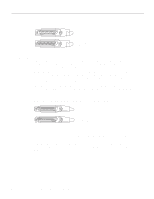
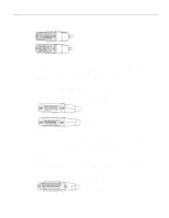
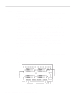
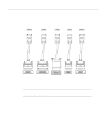
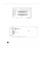
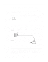
Network Connection Considerations Figure 2-20 Dual Serial Network Processor Module Ports LEDs (4 green) LEDs (4 green) LEDs (1 yellow, 1 green) DO TXC DI RXC DCD RS TS1 TS2 LP DCE P-0 P-1 SERIAL (V2) PORT-1 PORT-0 H1484a Alignment groove 50-Pin serial ports Alignment groove Two LED daughter cards are attached to the front of the dual serial module. (See Figure 2-21.) Figure 2-21 LEDs Dual Serial Network Processor Module-Top View Indicates port 0 LED daughter cards Mounting screw location Indicates port 1 Serial ports J5 J4 Port 1 Port 0 H1036a Module handle Caution Hold the dual serial network processor module carefully by its handle or by the module's edge. To prevent damage from stress or from ESD, do not exert force against the two LED daughter cards, and do not touch the components on the cards. Configuring the Dual Serial Module Interfaces The dual serial network processor module contains two jumpers, J4 and J5 (see Figure 2-21), which determine whether the ports are configured for nonreturn to zero (NRZ) or nonreturn to zero inverted (NRZI). J4 configures serial port 0, and J5 configures serial port 1. The factory-configured (default) jumper setting is for NRZ. To configure for NRZI mode on each port, the jumper must connect pins 1 and 2 of the respective jumper locations. (See Figure 2-22.) For NRZ (not NRZI), the jumpers that connect pins 2 and 3 can be removed. 2-20 Cisco 4000 Series Hardware Installation and Maintenance
-
 1
1 -
2
-
3
-
4
-
5
-
6
-
7
-
8
-
9
-
10
-
11
-
12
-
13
-
14
-
15
-
16
-
17
-
18
-
19
-
20
-
21
-
22
-
23
-
24
-
25
-
26
-
27
-
28
-
29
-
30
-
31
-
32
-
33
-
34
-
35
-
36
-
 37
37 -
 38
38 -
 39
39 -
 40
40 -
 41
41 -
 42
42 -
 43
43 -
 44
44 -
 45
45 -
 46
46 -
 47
47 -
48
-
49
-
50
-
51
-
52
-
53
-
54
-
55
-
56
-
57
-
58
-
59
-
60
-
61
-
62
-
63
-
64
-
65
-
66
-
67
-
68
-
69
-
70
-
71
-
72
-
73
-
74
-
75
-
76
-
77
-
78
-
79
-
80
-
81
-
82
-
83
-
84
-
85
-
86
-
87
-
88
-
89
-
90
-
91
-
92
-
93
-
94
-
95
-
96
-
97
-
98
-
99
-
100
-
101
-
102
-
103
-
104
-
105
-
106
-
107
-
108
-
109
-
110
-
111
-
112
-
113
-
114
-
115
-
116
-
117
-
118
-
119
-
120
-
121
-
122
-
123
-
124
-
125
-
126
-
127
-
128
-
129
-
130
-
131
-
132
-
133
-
134
-
135
-
136
-
137
-
138
-
139
-
140
-
141
-
142
-
143
 |
 |
