Cisco WS-X4624-SFP-E Hardware Maintenance Manual - Page 55
E1 Cabling, installed at J2 bypasses the AC-decoupling capacitor to ground
 |
UPC - 882658134944
View all Cisco WS-X4624-SFP-E manuals
Add to My Manuals
Save this manual to your list of manuals |
Page 55 highlights
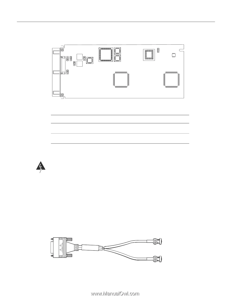
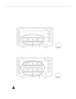
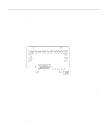
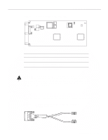
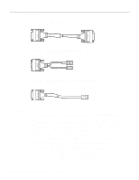
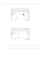
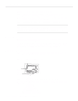
Figure 2-35 Location of Jumpers on the CE1 Module J2 J3 J4 J5 J7 Network Connection Considerations J1 H3146 E1 Cabling Table 2-7 Jumper Settings and Functions Jumper Position Function J2 1 and 2 Connects the Rx shield to chassis ground. 2 and 3 Connects the Rx shield through capacitive coupling to chassis ground. J1, J3, J4, 1 and 2 J5, J71 2 and 3 Sets cable impedance to 120-ohm Sets cable impedance to 75-ohm 1. All of these jumpers must be set to the same impedance. Warning To prevent problems with the E1 interface and to reduce the potential for injury, jumper J2 should be configured by trained service personnel only. For either impedance option, a jumper installed at J2 bypasses the AC-decoupling capacitor to ground, thereby coupling the interface directly to AC. This is a setting that could pose a risk of severe injury. By default and for safety, J2 has been configured with no ground. For the CE1 module, four serial cables are available from Cisco Systems. All three have DB-15 connectors on the CE1end and either BNC, DB-15, Twinax, or RJ-45 connectors on the network end. Figure 2-36, Figure 2-37, Figure 2-38, and Figure 2-39 show the E1 interface cables (respectively). Figure 2-36 E1 Interface Cable for 75-Ohm, Unbalanced Connections (with BNC Connectors) H2421 Preparing for Installation 2-33
-
 1
1 -
2
-
3
-
4
-
5
-
6
-
7
-
8
-
9
-
10
-
11
-
12
-
13
-
14
-
15
-
16
-
17
-
18
-
19
-
20
-
21
-
22
-
23
-
24
-
25
-
26
-
27
-
28
-
29
-
30
-
31
-
32
-
33
-
34
-
35
-
36
-
37
-
38
-
39
-
40
-
41
-
42
-
43
-
44
-
45
-
46
-
47
-
48
-
49
-
 50
50 -
 51
51 -
 52
52 -
 53
53 -
 54
54 -
 55
55 -
 56
56 -
 57
57 -
 58
58 -
 59
59 -
 60
60 -
61
-
62
-
63
-
64
-
65
-
66
-
67
-
68
-
69
-
70
-
71
-
72
-
73
-
74
-
75
-
76
-
77
-
78
-
79
-
80
-
81
-
82
-
83
-
84
-
85
-
86
-
87
-
88
-
89
-
90
-
91
-
92
-
93
-
94
-
95
-
96
-
97
-
98
-
99
-
100
-
101
-
102
-
103
-
104
-
105
-
106
-
107
-
108
-
109
-
110
-
111
-
112
-
113
-
114
-
115
-
116
-
117
-
118
-
119
-
120
-
121
-
122
-
123
-
124
-
125
-
126
-
127
-
128
-
129
-
130
-
131
-
132
-
133
-
134
-
135
-
136
-
137
-
138
-
139
-
140
-
141
-
142
-
143
 |
 |