Cisco WS-X4624-SFP-E Hardware Maintenance Manual - Page 58
Inspecting the System, This product meets the Class 1 Laser Emission Requirement from CDRH FDDI.
 |
UPC - 882658134944
View all Cisco WS-X4624-SFP-E manuals
Add to My Manuals
Save this manual to your list of manuals |
Page 58 highlights
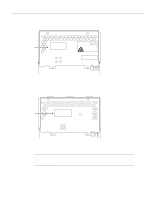
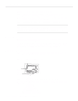
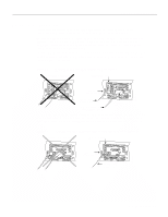
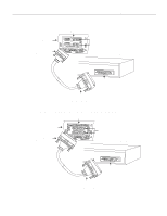
Inspecting the System Note The ATM processor module for the Cisco 4000 series router uses identical duplex SC connectors for single mode and multi-mode SONET connections. The front panels are similar in appearance. The best way to tell the difference is the yellow laser warning label on the single-mode module's front panel, or the specific part number visible on the upper surface of all PLIMs. Warning Invisible laser radiation can be emitted from the aperture ports of the single-mode ATM products when no fiber-optic cable is connected. Avoid exposure and do not stare into open apertures. This product meets the Class 1 Laser Emission Requirement from CDRH FDDI. Inspecting the System Before unpacking the system, make certain that you are prepared to install it. If the final installation site is not ready, keep the chassis in its shipping container to prevent accidental damage. After determining where you want the system installed, proceed with the unpacking. The router, cables, publications, and any optional equipment you ordered might be shipped in more than one container. When you unpack each shipping container, check the packing list to ensure that you received all of the following items: • Router • 6-foot (1.8-meter) power cord • Bag of rubber feet for desktop mounting • Optional equipment (which might include network connection cables) • This publication, optional companion publications, or UniverCD , as specified by the customer order Inspect all items for shipping damage. If anything appears damaged, or if you encounter problems when installing or configuring your system, contact a customer service representative. Also, please complete and mail your Product Registration (found in the Warranty Package). 2-36 Cisco 4000 Series Hardware Installation and Maintenance
-
 1
1 -
2
-
3
-
4
-
5
-
6
-
7
-
8
-
9
-
10
-
11
-
12
-
13
-
14
-
15
-
16
-
17
-
18
-
19
-
20
-
21
-
22
-
23
-
24
-
25
-
26
-
27
-
28
-
29
-
30
-
31
-
32
-
33
-
34
-
35
-
36
-
37
-
38
-
39
-
40
-
41
-
42
-
43
-
44
-
45
-
46
-
47
-
48
-
49
-
50
-
51
-
52
-
 53
53 -
 54
54 -
 55
55 -
 56
56 -
 57
57 -
 58
58 -
 59
59 -
 60
60 -
 61
61 -
 62
62 -
 63
63 -
64
-
65
-
66
-
67
-
68
-
69
-
70
-
71
-
72
-
73
-
74
-
75
-
76
-
77
-
78
-
79
-
80
-
81
-
82
-
83
-
84
-
85
-
86
-
87
-
88
-
89
-
90
-
91
-
92
-
93
-
94
-
95
-
96
-
97
-
98
-
99
-
100
-
101
-
102
-
103
-
104
-
105
-
106
-
107
-
108
-
109
-
110
-
111
-
112
-
113
-
114
-
115
-
116
-
117
-
118
-
119
-
120
-
121
-
122
-
123
-
124
-
125
-
126
-
127
-
128
-
129
-
130
-
131
-
132
-
133
-
134
-
135
-
136
-
137
-
138
-
139
-
140
-
141
-
142
-
143
 |
 |
